INSTALLATION
INSTALLATION
33
33
2.14e Slew Transmitter Location
The slew transmitter is connected to the slew
encoder with a 6 ft. cable but it can be installed
beside the transmitter if convenient; the cable can
be cut to the length required.
2.14f Slew Transmitter Installation
1. Screw the slew transmitter to a flat surface with
1/4 in. screws.
2. If needed, weld pads can be used to facilitate
transmitter installation.
3. Tie wraps can be used to secure the cable
between the encoder and transmitter.
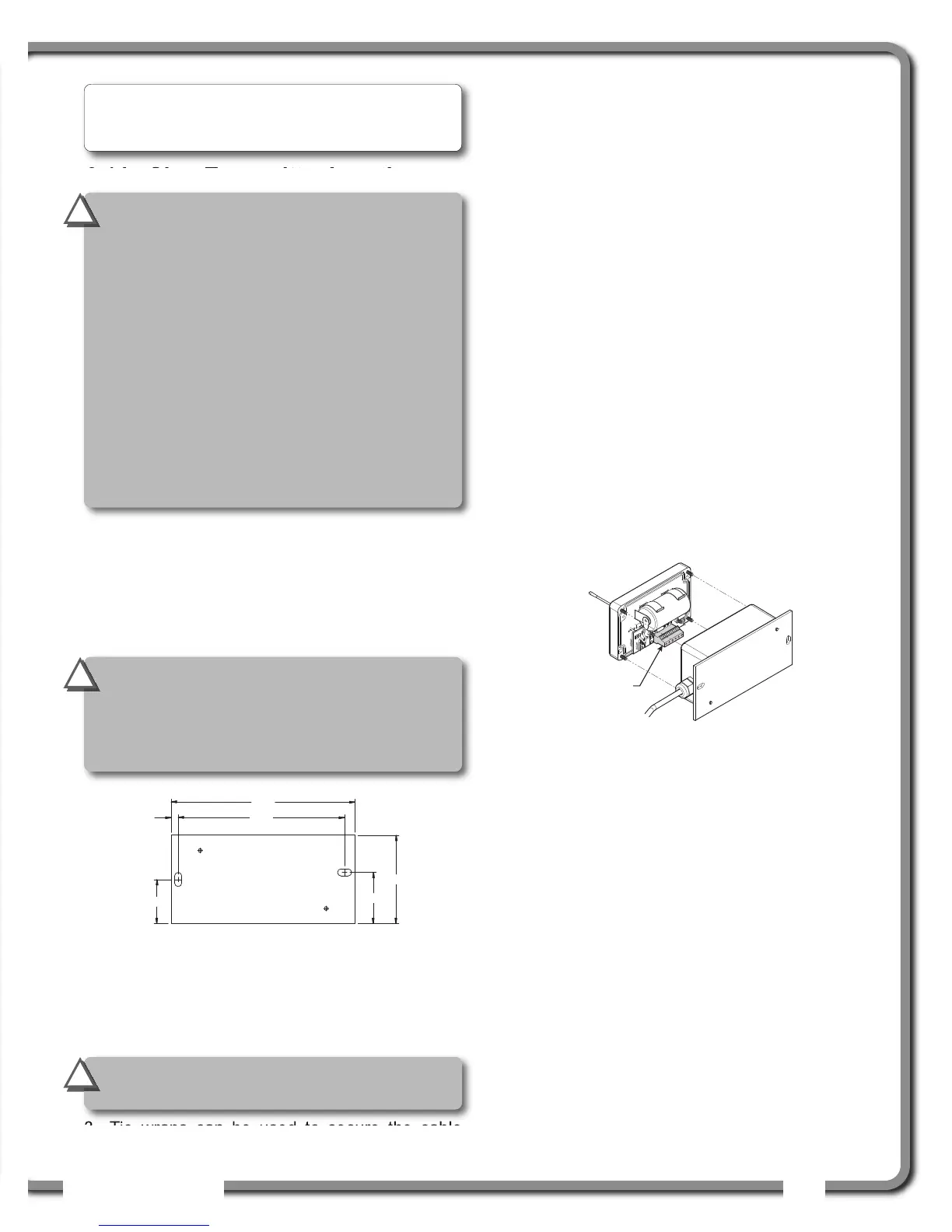
2.14g Cable Length Adjustment
If the cable between the encoder and transmitter is
too long, it can be cut to the desired length;
1. Remove the cover from the transmitter using
either a flat or a Phillips № 2 screwdriver.
2. Using a small flat screwdriver, loosen the 6 screws
of the terminal block and remove the wires from it.
Lay down the transmitter cover on a clean surface.
3. Loosen the cable gland with a 3/4 in. wrench and
pull the cable from the inside of the transmitter box
until you reach the desired length. Tighten the gland
back with the wrench. Do not to overtighten.
4. Cut the cable excess, leaving about 4 in. in the
transmitter box. Remove the sheath to about 2 in.,
remove the shield and remove the individual
sheaths on the 6 wires to about 1/4 in. Connect
the 6 wires in the terminal block respecting the
color codes and tighten the terminal block screws.
5. Replace the transmitter cover and screw it in place.
6. Test the sensor for proper function: start-up
the display and move the encoder wheel.
2.15
2.15
Slew sensor calibration
Slew sensor calibration
The slew sensor need to be calibrated on the crane
where it is installed on before utilisation.
1. Go to Menu 4B1A), select the slew sensor and
press Enter. Press Next to start the slew
calibration wizard.
2. Menu 1/5) CRANE GEAR TEETH: Enter the teeth
count of crane’s slew gear.
3. Menu 2/5) SENSOR GEAR TEETH: Enter the teeth
count of the gear of the slew sensor installed.
4. Menu 3/5) ADJUST/CONFIRM SLEW VALUE: Enter the
current position of the slew (swing).
5. Menu 4/5) REVERSED ROTATION: Depending on how
the slew sensor is installed, the rotation direction
may be reversed. The slew value should go up
when you swing to right (clockwise).
6. Menu 5/5) PRESS ENTER TO SAVE CALIB IN SENSOR:
the settings will be saved in the sensor.
Note: The tension applied by the slew encoder
spring is required to keep the encoder gear in
contact with the slew gear.
IMPORTANT!
To ensure reliable radio
communication between the slew sensor
and the GS550 display, the following
conditions must be respected:
• The antenna of the slew transmitter should
not be in contact with metal.
•The antenna should point to the left or to the
right of the boom; it should not point directly
to, or away from, the GS550 display.
•The antenna should have a clear line of sight
to the GS550 display; in most cases this
means mounting the transmitter outside of
the crane structure on the same side of the
boom as the operator's cab.
!
!
IMPORTANT!
Do not weld in proximity to
LSI
LSI sensor/transmitters.
!
!
IMPORTANT!
The transmitter must be
installed such that it does not interfere with
the crane through all normal movements. It may
be installed at any angle as long as the cover can
be removed when required to change the battery.
!
!
6,50
3,13
,25
5,88
1,56
1,81
Gland
side
Figure: Slew transmitter. Dimensions are in inches. Not to scale.
Figure: Cable length adjustment.

 Loading...


