OPERATION
OPERATION
11
11
INSTALLATION
INSTALLATION
2.3
2.3
Angle Sensors for the
Angle Sensors for the
Boom or Jib
Boom or Jib
2.3a Mounting Procedure
The GS010 series angle sensors can be turned on
by starting up the GS550 display to which they are
programmed. The angle sensor can then assist in
levelling itself with the red and green LED.
1. Determine the angle sensor position.
a. The GS010-01 boom angle sensor can
be mounted on either side of the boom.
b. The GS010-02 360° angle sensor must
be mounted on the port side of the jib.
c. The angle sensor must be level with the
boom or jib centerline.
d. The top / bottom axis of the angle sensor
must be within 15 degrees of vertical
e. The angle sensor should have a clear line
of sight to the cabin mounted display.
f. The angle sensor antenna should not
contact a metal object.
2. Install the welding pads; keep the angle sensor
at least three feet from the weld site and any
connecting metal objects while welding.
3. Mount the angle sensor to the weld pads with
the screws and washers provided.
4. Verify angle indication on the GS550 LCD.
5. If the angle displayed by a GS010-01 boom
angle sensor is a high negative value, then tilt
the angle sensor up over 45 degrees, and then
tilt back down to horizontal. The GS010-01
boom angle sensor will automatically detect on
which side of the boom it is installed and correct
angle indication accordingly.
2.3b Angle Calibration Procedure
№ 1: Mechanical Set-Up
1. Level the boom such that it is perfectly
horizontal; use a high quality bubble or digital
angle sensor. If the GS550 display indicates 0.0
degrees then angle calibration is complete; if
not then continue to step 2.
Cabin
Boom
Angle Sensor
Boom
C
L
Boom
Angle Sensor
Cabin
Boom
Angle Sensor
Cabin
Wedge
Figure: Angle sensor level with the boom (typical installation) -
Side View
Figure: Angle sensor top/bottom axis within 15° of vertical
(typical installation) - Front View
Figure: Wedge used to mount the angle sensor with its
top/bottom axis within 15° of vertical (typical
installation) - Front View
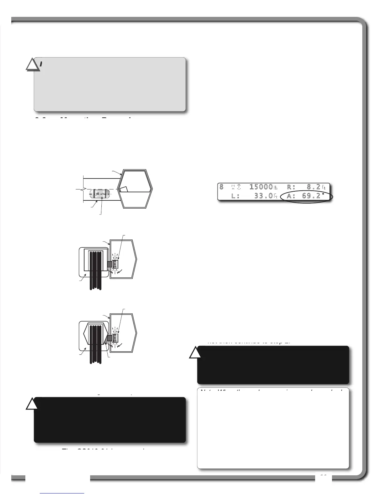
Figure: Typical operation page with boom angle indication
8 15000 R: 8.2
L: 33.0 A: 69.2°
Note: When the angle sensor is moved very slowly,
it may take several seconds to see an update at the
GS550 display. Instead move the sensor up a
couple of degrees, and then bring it back down to
where it should be. The small light on the angle
sensor flashes when it transmits a new value to the
display. To assist at the calibration, the angle sensor
could be set to transmit continuously for 5 minutes
by entering the automatic calibration menu 4B1 and
by selecting the angle sensor.
IMPORTANT!
Keep the angle sensor away
from the boom and any connecting metal
structures when welding the metal lugs to
the boom. Proximity to welding may cause
permanent damage to the angle sensor and
prevent accurate angle indication.
!
!
WARNING!
The angle reading may be
affected by vibration and may fluctuate; the
angle sensor should not be installed in close
proximity to a high RPM electric motor or other
source of high frequency vibration.
!
!
WARNING!
Failure to ensure the boom is
levelled will result in false reading of the
crane’s radius hence the risk of structural
failure of the crane or crane tipping over.
!
!

 Loading...


