32
32
The GS550 System
The GS550 System
2.14
2.14
Slew Sensor Installation
Slew Sensor Installation
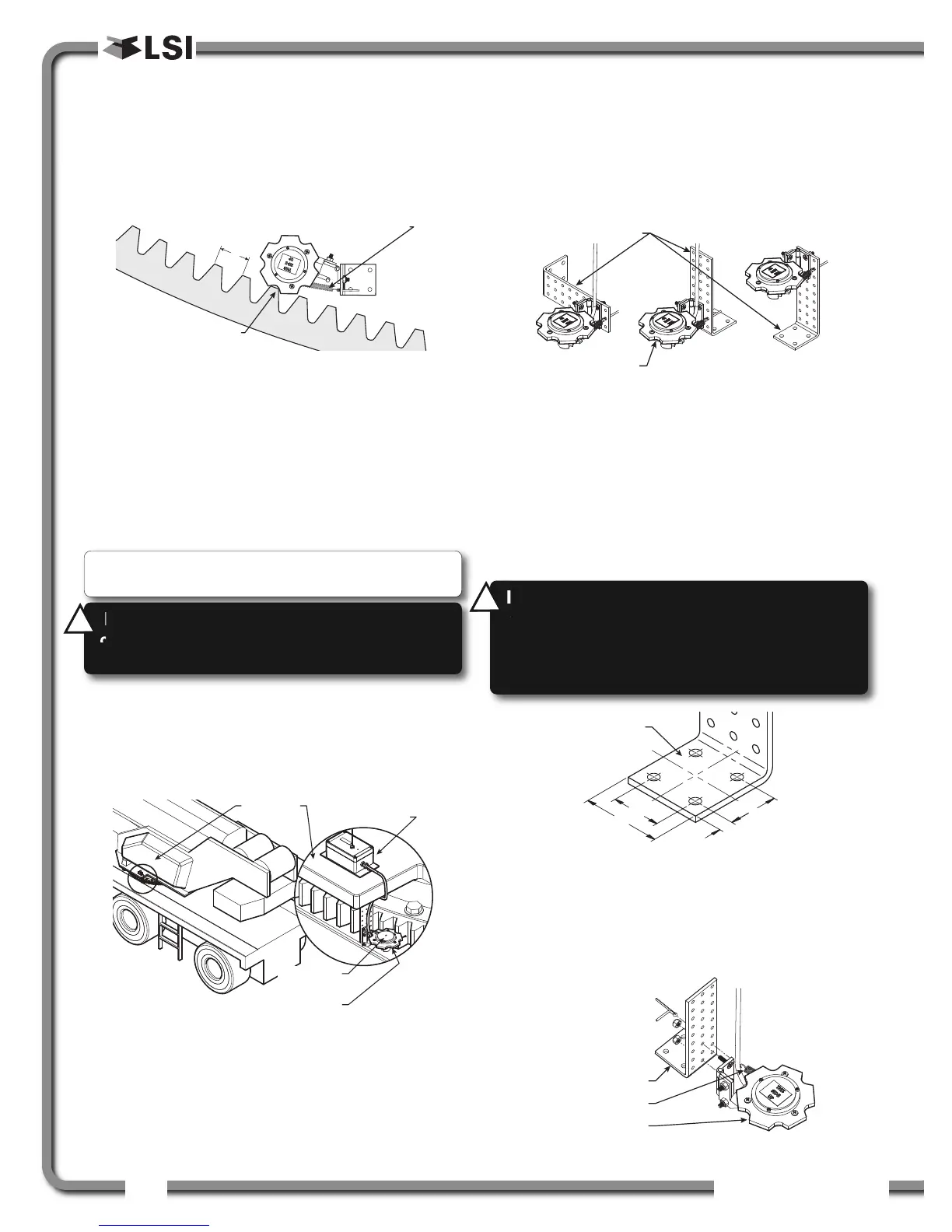
2.14a Encoder Gear Verification
Verify that the slew (swing) sensor was supplied with
the correct gear for your application;
a. Roll the encoder gear on the crane slew
gear; it should roll without skipping.
b. The distance between the leading edges (X)
of the slew gear teeth should correspond to
the gear model shipped with your order.
Example: P/N PA133-01 corresponds to a
slewgear with teeth leading edges 2 in. apart.
2.14b Slew Encoder Location
1. Install the slew encoder near the crane slew
gear where it will roll freely on the slew gear
when the crane slews.
2. Make sure that the slew encoder does not come
into contact with any other parts of the crane
through the full motion of the crane upper body.
2.14c Slew Encoder Orientation
The slew encoder bracket is designed so that the
encoder can be installed on either bottom, top or
side surfaces. If the surface on which the sensor is
to be installed is not at a square angle to the slew
gear, the mounting plate can be bent and/or cut.
2.14d Slew Encoder Installation
1. Find a rigid, level space near the slew gear to
install the slew encoder mounting bracket.
2. Weld the mounting bracket in place or install
with 1/4 in. screws. The screws can be installed
directly on the crane plate or a custom weld pad
can be built and welded on the crane.
3. Once the mounting bracket is installed, screw
on the encoder with the nuts and bolts provided.
Put tension on the spring by inserting the cotter
pin in the middle hole in front of the hinge.
Note: The slew sensor can be installed on either
internal or external tooth slew gears.
x
Encoder gear rolls
on the tooth edges
This spring needs to be in tension and keeps the
slew encoder gear in strong contact with the slew gear
Figure: Encoder gear verification.
Crane Upper
Body
Slew Sensor
Transmitter GS030
Slew Sensor
Encoder GS031
This side up in
wet locations
Figure: Slew encoder location. Typical installation.
Slew Sensor Encoder
Slew Encoder Bracket
Figure: Slew encoder bracket orientation.
WARNING!
Keep the slew encoder away from
any connecting metal structures when welding
mounting bracket to the boom. Proximity to
welding may cause permanent damage to the
slew encoder and render the system unsafe.
!
!
Figure: Mounting bracket footprint. Dimensions are in inches.
Slew Sensor Encoder
Slew Encoder Spring
Slew Encoder Bracket
Figure: Slew encoder installation. Typical installation.
WARNING!
Missing or damaged teeth on the
crane slew gear will prevent proper operation of
the slew sensor and render the system unsafe.
!
!

 Loading...


