16
16
The GS550 System
The GS550 System
and attach to the cable anchor on the tip of the
last boom section. If additional cable length is
required to reach the cable anchor point
remove winds from the reel without putting
additional tension on the cable reel spring.
There should be minimal tension on the cable
reel spring when the boom is fully retracted.
6. Verify the boom length indicated on the GS550
LCD. Boom length is indicated following the
length abbreviation “L”, typically on the first or
second display operation page. Boom length
indicated should equal the actual total boom
length. The actual boom length is the distance
from the boom base pin to the head sheave
centre as measured along the boom centreline.
Depending on the exact placement of the cable
reel and the cable anchor the displayed length
may differ from the actual length.
2.5c Boom Length Calibration
Procedure № 1: Mechanical
Set-Up
1. Fully retract the boom
2. Adjust the loose wire rope at the boom tip so
that the displayed boom length matches the
actual boom length.
3. Fully extend the boom
4. Verify the boom length indicated at full boom
extension matches the actual fully extended
boom length. If not then follow Boom Length
Calibration Procedure № 2: Correct with the
GS550.
2.5d Boom Length Calibration
Procedure № 2: Correct with
the GS550
If the displayed boom length does not match the
actual length of the boom retracted or extended and
if it is not possible to easily correct by following 2.6c
Boom Length Calibration Procedure № 1, then
follow this procedure. This procedure is completed in
the operators cab, it requires fully retracting, and
then fully extending the boom, as prompted by the
on screen instructions.
1. Go to menu 4B) SENSOR CALIBRATION.
2. Press Enter to go to the password page.
3. Enter the user password and press Enter twice
to go to menu 4B1A).
4. Use Back and Next to select the length sensor,
and then press Enter to confirm communication
with the sensor is possible.
5. Press Next to start the wizard.
6. Note the units that will be used during the
calibration wizard, and then press Next.
7. Fully retract the boom, and then press Next.
8. Use Up and Down to adjust the length value
displayed to equal the actual fully retracted
boom length, and then press Next.
9. Fully extend the boom, and then press Next.
10.Use Up and Down to adjust the length value
displayed to equal the actual fully extended
boom length, and then press Next.
11. Note the new trim value, and then press Next.
12.Note the new scale value, and then press Next.
13.Press Enter to send the new calibration to the
length sensor.
14.Press Exit three times to return to the operation
display.
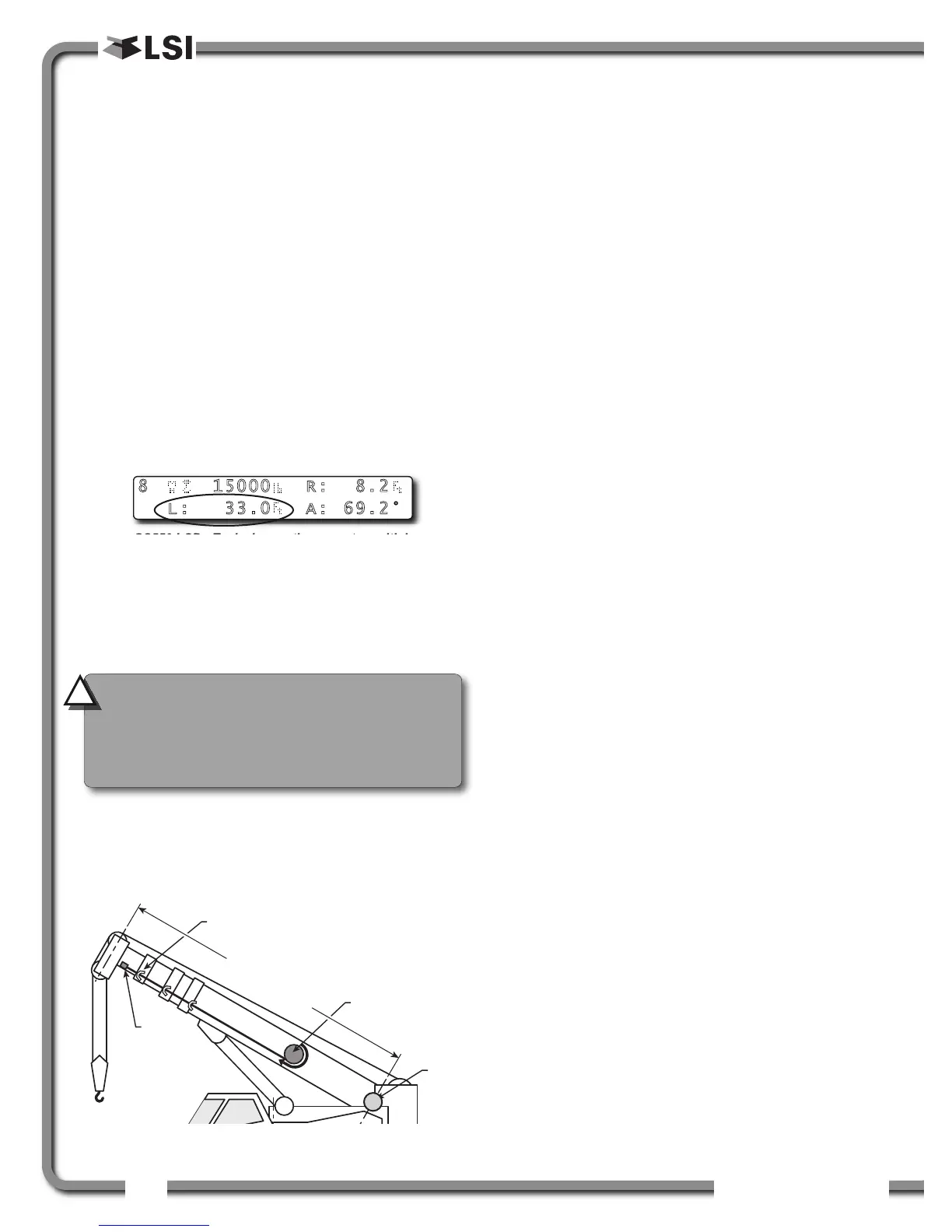
Figure: GS550 LCD - Typical operation page two with boom
length indication
Cable
anchor
Cable guide
Cable
reel
Boom length
Boom
base
pin
Figure: The actual boom length. typical installation.
8 15000 R: 8.2
L: 33.0 A: 69.2°
CAUTION!
Visually monitor remaining
length on the cable reel as the boom is
extended for the first time following
installation. This generally requires a second
person (in addition to the operator).
!
!

 Loading...


