30
30
The GS550 System
The GS550 System
2.13
2.13
Rope payout
Rope payout
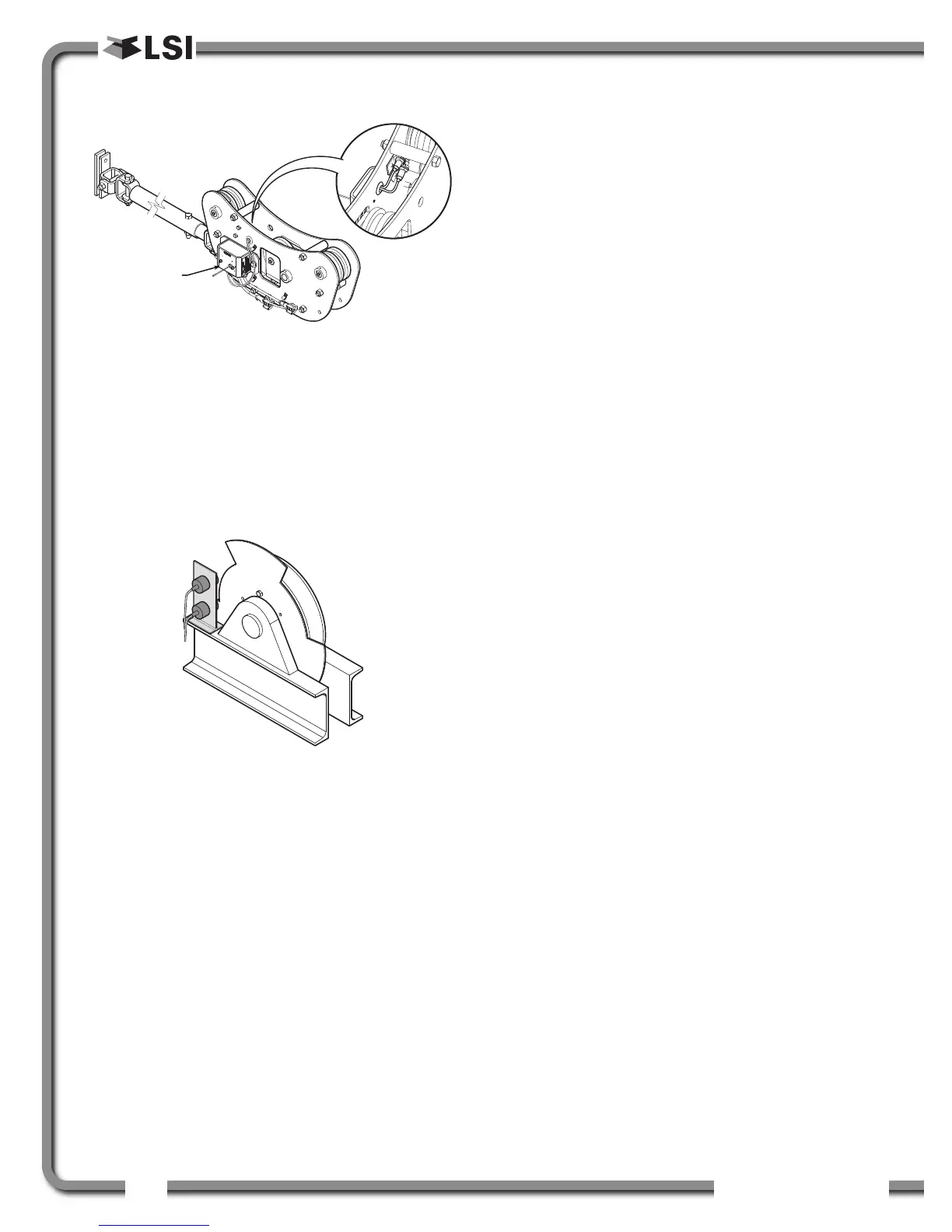
Typically the rope payout sensor is factory installed
on the line riding tensiometer load sensor (figure
above). Alternatively the rope payout sensor may
be installed on an appropriate sheave (figure
below). Power supply must be provided to the rope
payout sensor. A GS550 display can then be
programmed to communicate with the sensor and
to indicate rope payout (length) and rope speed.
Zero the rope payout using the Tare menu before
calibration.
2.13a Rope Payout Calibration
Procedure № 1: Mechanical
Set-Up
1. Hoist up to reel in the wire rope fully.
2. Install the rope payout system.
3. Zero the rope payout length in the Tare menu
4. Hoist down to pay out a known length of wire
rope (for example: 20 feet).
5. Verify the rope payout indicated matches the
actual length of wire rope paid out. If not then
follow Rope Payout Calibration Procedure № 2.
2.13b Rope Payout Calibration
Procedure № 2: Correct with
the GS550
If rope payout indicated does not match actual rope
payout, and if it is not possible to easily correct by
following Rope Payout Calibration Procedure № 1,
then follow this procedure. This procedure requires
hoisting up to fully reel in the wire rope, and then
hoisting down to pay out a known length of wire
rope. For accurate calibration the “known length”
paid out must be accurately measured.
1. Go to menu 4B) SENSOR CALIBRATION and press
Enter.
2. Enter the user password and press Enter twice
to go to menu 4B1A).
3. Use Back and Next to select the rope payout
sensor, and then press Enter to confirm
communication with the sensor is established.
4. Press Next to start the wizard.
5. Note the units that will be used during the
calibration wizard, and then press Next.
6. Hoist up (pay in) the wire rope and then press
Next.
7. Use Up and Down to adjust the actual wire
rope payout length and then press Next.
8. Hoist down (payout) the wire rope and then
press Next.
9. Use Up and Down to adjust the actual wire
rope payout length and then press Next.
10.Note the new trim value, and then press Next.
11. Note the new scale value, and then press Next.
12.Press Enter to save and send the new
calibration to the rope payout sensor.
13.Press Exit four times to return to the operation
display.
Figure: Rope payout on a line riding tensiometer
Figure: Alternative installation of a rope payout

 Loading...


