OPERATION
OPERATION
39
39
Information Menu Alerts (Continued)
Alert:
Description:
Voltage is not detected on the lockout wire when safe**.
With the standard relay configuration voltage should be
present on a lockout wire in safe condition.
• Verify the wire is not shorted to ground.
•Verify the wire is not connected directly to the
valve coils; a relay should be installed between
the wire and the valve coils. Refer to the Power
Supply and Lockout Connection sub section of
this manual.
Alert:
Description:
One or more primary conditions of the chart selected for
the hoist is not met (example: telescopic boom length).
•Verify the conditions of the selected rated capacity
chart.
Alert:
Description:
The boom or jib angle is above the maximum angle
permitted by the selected chart. (For charts determined
by radius only, this message will occur when the radius
is less than the minimum radius permitted by the chart).
•Verify the boom and jib angles permitted by the
rated capacity chart selected.
Alert:
Description:
The boom or jib angle is under the minimum angle
permitted by the selected chart. (For charts determined by
radius only, this message will occur when the radius is
greater than the maximum radius permitted by the chart).
•Verify the boom and jib angles permitted by the
rated capacity chart selected.
**If the lockout relay is inverted this alert will occur
when voltage is not detected on the wire in alarm.
3.3c Limit
Set Hoist Limits
Press Limit and then Enter to access the Sensor Limits
menu. The Sensor Limits menu displays the limits for
each sensor in the sensor list on successive pages.
Use Next to scroll from one limit to the next.
Use Up and Down to adjust a limit.
When using the GS550 as a load indicator without
programmed crane specific rated capacity charts the
load limit is typically set to the lesser of the rope limit,
the hoist limit, and the maximum allowed capacity
as determined from the capacity charts.
When using the GS550 as a rated capacity indicator
with programmed crane specific rated capacity
charts the load limit is typically set to the lesser of
the rope limit and the hoist limit.
Set Work Area Limits
The Work Area Limits menu is only available if a
slew, radius or tip height is configured in the system.
Press Limit, Next and then Enter to access the
Work Area Limits menu. To program fixes and
dynamics limits, refer to section 3.9 Work Area
Management Programmation.
3.4
3.4
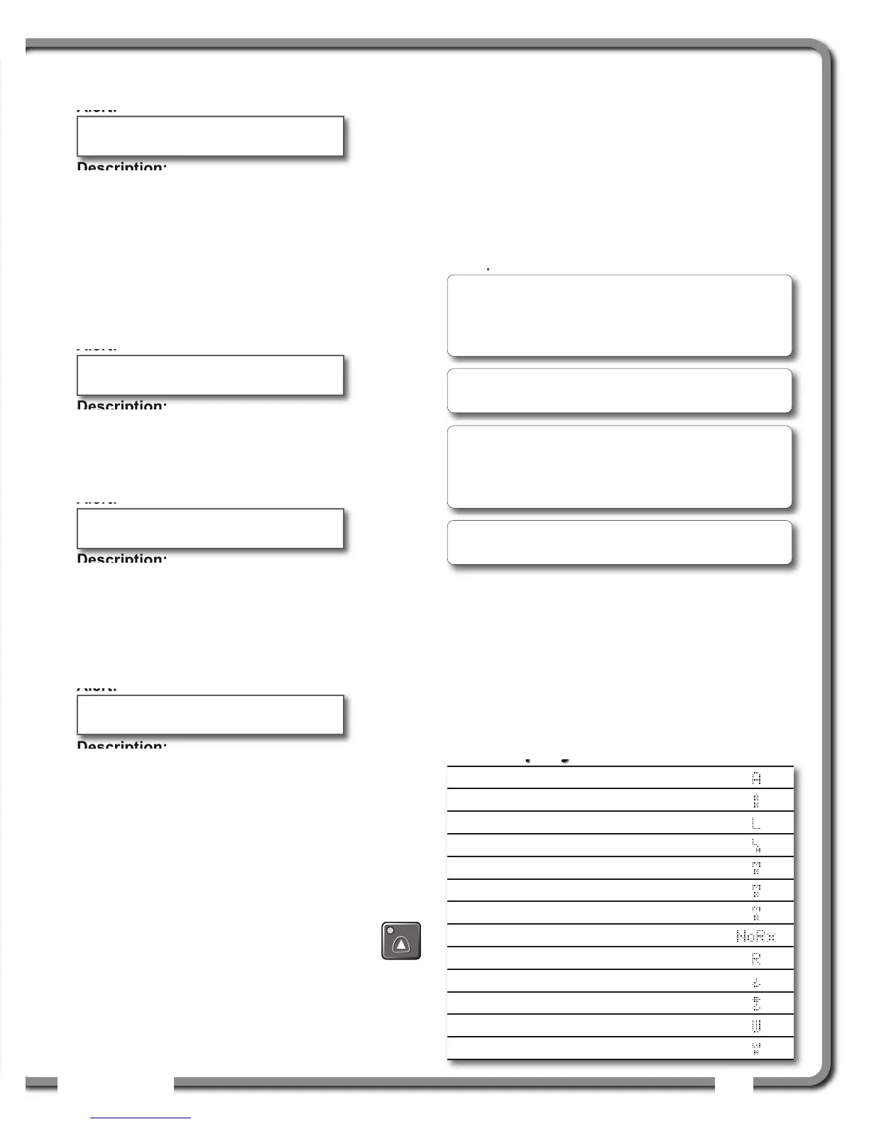
Display abbreviations
Display abbreviations
Verify white wire
(shorted to ground)
Main
Out of chart
Main angle
above chart maximum
Main angle
below chart minimum
Angle
Auxiliary hoist
Length
Luffing angle
Main hoist
Maximum
Maximum or minimum angle
Communication not established
Radius
Tare (net weight)
Gross weight
Wind speed
Whip hoist
Note: Press Up and Down simultaneously to
return a limit to the factory default setting. The
factory default maximum limit for load sensors is
10 000 lb per part of line.
Note: When the weight units are tons the minimum
load limit increment is 0.1 ton per part of line.
Note: The limits set in the limit menu are different
than those set in the work area limits; the limits set
in Limit menu will stay active even if no work area
has been defined.
Note: to desactivate the permanent slew limits in the
limit menu, the right and left limit should be set to 0.

 Loading...


