OPERATION
OPERATION
13
13
INSTALLATION
INSTALLATION
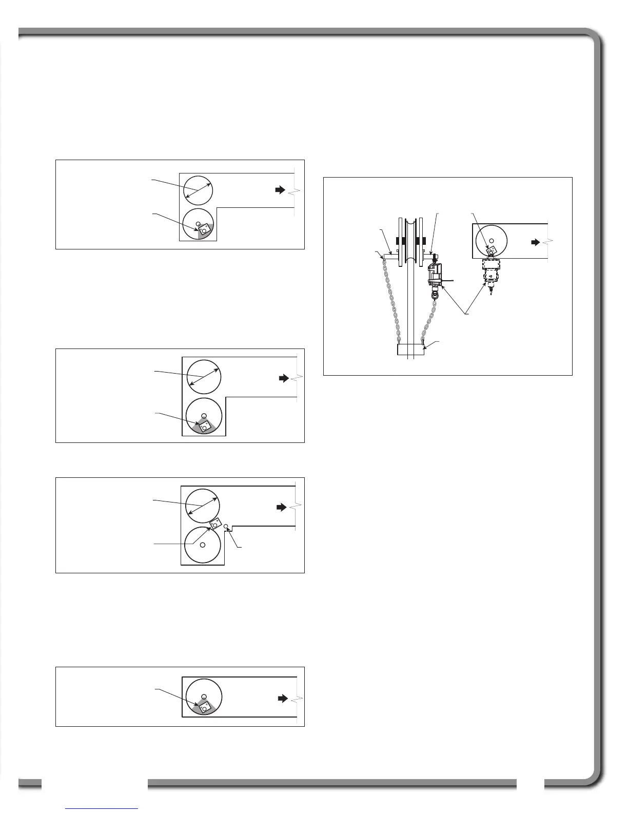
Position the sensor mounting bracket. To ensure that
the sensor can pivot securely on the mounting
bracket throughout the full range of boom angle, the
mounting bracket must be positioned at a 30° from
horizontal with the boom parallel to the ground and
such that the locking pin of the mounting bracket
points up. Bolt or weld securely.
If the head sheave diameter is between 8 and 16
inches (20-41 centimetres) then two mounting
brackets will be required to permit both live and dead
end mounting.
For live end mounting on multiple sheave blocks with
sheaves greater than 16 inches (41 centimetres) in
diameter consult your service representative.
For fast line weight installation place the anti-two-
block switch mounting bracket directly below the
sheave center as low and as close to the edge of
the sheave as possible. Place the fast line weight
mounting bracket on the opposite side of the
sheave with the chain hole pointing down and lined
up opposite the pivot of the anti-two-block switch
mounting bracket.
2.4b GS050 Installation
1. Mount the GS050 on the bracket and verify that
the GS050 can rotate freely through all possible
boom movements without being able to come
off the bracket.
2 . Install the weight and chain assembly around
the cable and attach the other end of the chain
to the GS050. Tighten all the chain links of the
chain assembly.
3. Adjust chain length as required, see sub-section
Chain length adjustment.
4. Test system function.
Up to 8 in. (20 cm)
diameter
Boom
base
Mount bracket below
and behind sheave
center.
Figure: Anti-two-block switch placement on a telescopic boom
8-16 in. (20-41 cm)
diameter
Boom
base
Mount bracket 4 in.
(10 cm) below sheave
center.
Figure: Anti-two-block switch placement for live end mounting
on a lattice boom
8-16 in. (20-41 cm)
diameter
Boom
base
Dead
end pin
Mount bracket 4 in.
(10 cm) in front of the
dead end pin.
Figure: Anti-two-block switch placement for dead end
mounting on a lattice boom
Boom
base
Mount bracket 4 in.
(10 cm) below sheave
center.
Figure: Jib, rooster or other extension; anti-two-block switch
placement for single part of line operation only
Boom
base
Mount bracket directly
below sheave
center as low as
possible.
Fast line
mounting
bracket
Fast line
weight
Switch bracket
Front View
Chain
hole
Figure: Fast line weight installation

 Loading...


