28
28
The GS550 System
The GS550 System
2.12
2.12
List and Trim Angle
List and Trim Angle
Sensor
Sensor
The GS010-03 is a two axis angle sensor designed
to detect both list and trim angle. Minimum and
maximum limits for list and trim angle are
adjustable in the display. The display will generate
an alarm if the limits are exceeded and can be
programmed to generate lockout. Furthermore list
and trim angle can be used to control rated
capacity chart selection where required (example:
barge cranes).
2.12a Programming the GS550 for
List and Trim Indication
For list indication, add the GS010-03 ID number to
the sensor list (menu 4A1) and select the sensor
type “List sensor”.
For trim indication, add the GS010-03 ID number to
the sensor list (menu 4A1) and select the sensor
type “Trim sensor”.
The maximum and minimum angles for list and trim
indication can be adjusted in the limit menu. The
default limits are 10.0° maximum and -10.0°
minimum.
2.12b Mounting Instructions
1. Determine the angle sensor position.
a. The mounting surface should be flat and
known to be level (0°) in both the list and
trim axes.
b. The angle sensor should have a clear line
of sight to the cabin mounted display.
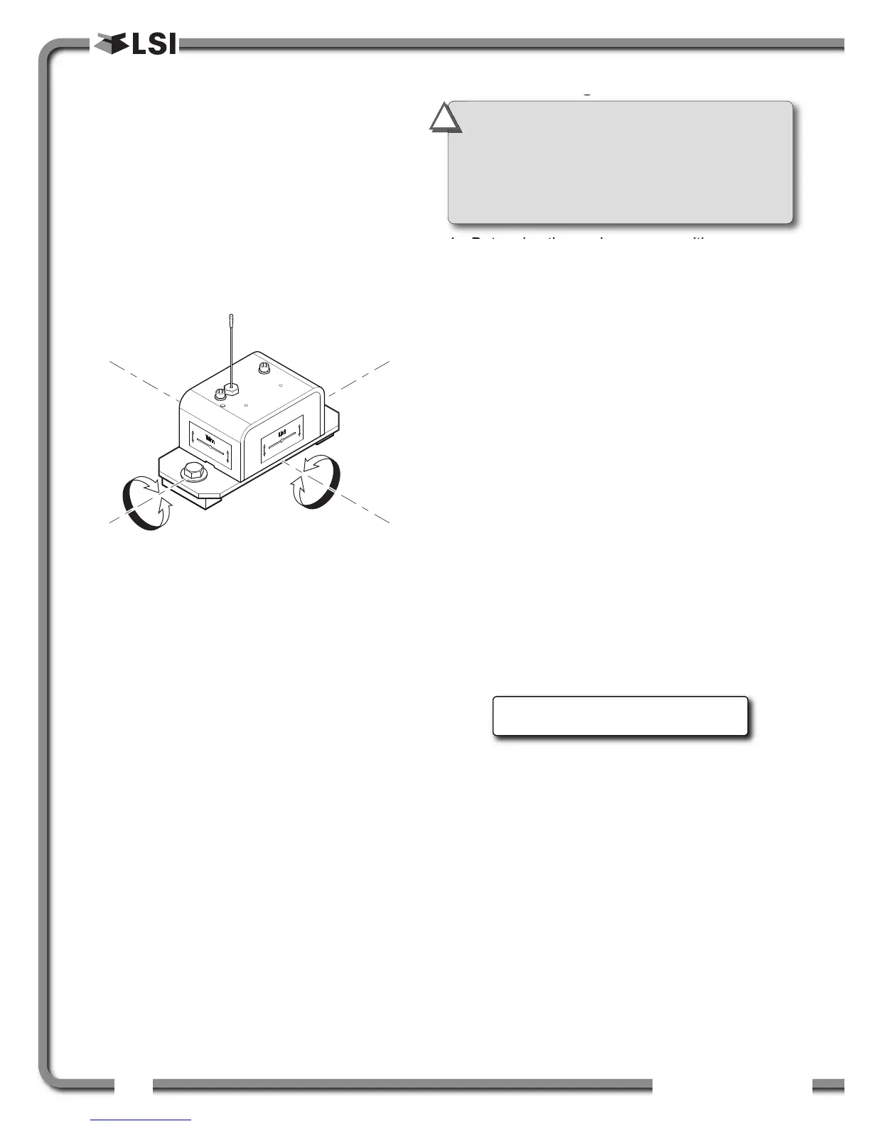
c. The angle sensor should be installed
horizontally, with the antenna pointing up.
d. The list and trim axes are indicated on the
angle sensor, follow these indications to
orient the sensor correctly for accurate list
and trim indication.
e. The angle sensor antenna should not
contact a metal object.
2. Install the welding pads; keep the angle sensor
well removed from the weld site and any
connecting metal objects while welding.
3. Mount the angle sensor to the weld pads with
the screws and washers provided.
4. Verify list and trim angle indication by the
GS550; in operation display, use Next to
advance to the list and trim indication page.
Figure: Trim and list angle indication
Trim angle: 0.5°
List angle: -1.2°
Figure: List and Trim axes
IMPORTANT!
Remove the angle sensor
from any connecting metal structures or
surfaces when welding the metal lugs to the
mounting surface. Proximity to welding may
cause permanent damage to the angle sensor
and prevent accurate angle indication.
!
!

 Loading...


