MAINTENANCE/SERVICE
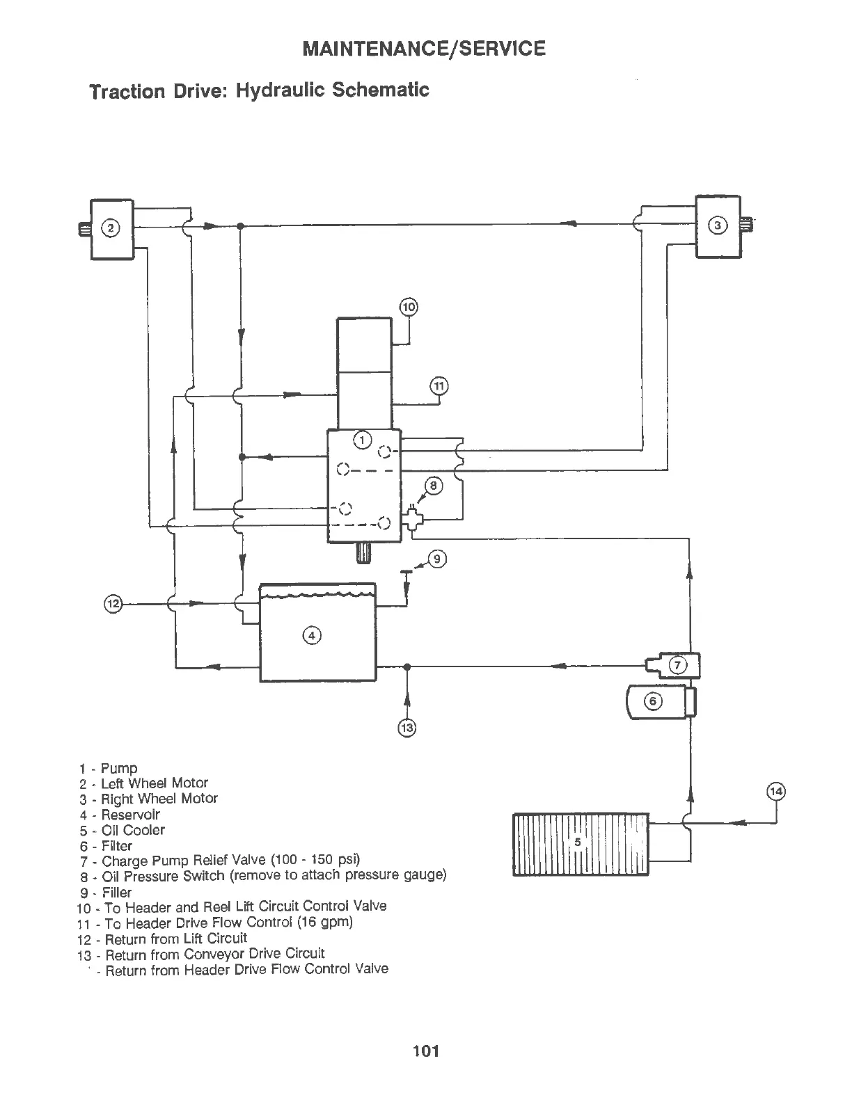
Traction Drive: Hydraulic Schematic
11
0 -1-
--t
!---
--------~
1 - P
ump
2 - Left Whe
el
Mot
or
3 - Right Wheel M
otor
4 - Reservoir
5 - Oil Cooler
6 - F
il
ter
13
7 - Charge Pump Relief Valve (100 - 150 psi)
8 - Oil Pressure Switch (remove
to
attach pressure gauge)
9 - Filler
10 -
To
Header and Reel Lift Circuit Control Valve
11
-
To
Header Drive Flow Control
{16
gpm)
12 - Return from Lift Circuit
13 - Return from Conveyor Drive Circuit
· - Return from Header Drive Flow Control Valve
101