MAINTENANCE/SERVICE
Header Drive: Hydraulics
HEADER
DRIVE
RELIEF
PRESSURES
Should problems be encountered with
one
of
the
header hydraulic circuits,
check
relief pressures
as
fol
lows
: ·
Harvest
Header
and
Multi-Crop
Header
To
check
relief pressure
at
reel
circuit
relief valve
(C)
or
conveyor
circuit relief valve (D):
1. Attach a 3000 psi (20 MPa) pressure gauge
to
a hose
that
Is
long
enough
to
allow
pressure
gauge
to
be
read
from
the
operator's seat.
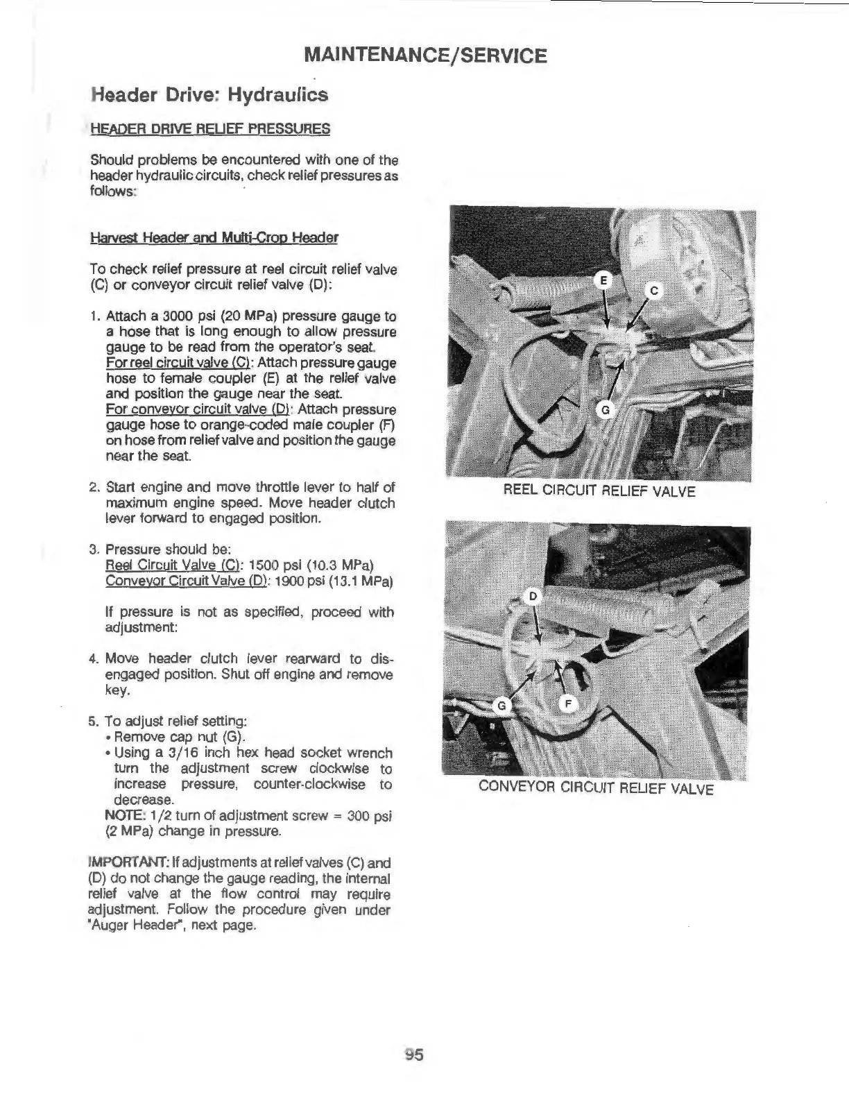
For
reel circuit valve (C): Attach pressure gauge
hose
to
female
coupler
(E)
at
the relief valve
and position
the
gauge near
the
seat.
For
conveyor circuit valve (D): Attach pressure
gauge
hose
to
orange-coded male coupler
(F)
on
hose
from relief valve
and
position
the
gauge
near
the
seat.
2. Start engine
and
move
throttle lever
to
half
of
maximum engine speed. Move header clutch
lever forward
to
engaged position.
3. Pressure should
be:
Reel Circuit Valve (C): 1500 psi (10.3 MPa)
Conveyor Circuit Valve
(D): 1000 psi (13.1 MPa)
If
pressure is
not
as
specified, proceed with
adjustment:
4. Move header clutch lever rearward
to
dis-
engaged position. Shut
off
engine and remove
key.
5.
To
adjust relief setting:
• Remove cap
nut
(G).
• Using a
3/16
inch hex head socket wrench
turn
the
adjustment screw clockwise
to
increase pressure, counter-clockwise
to
decrease.
NOTE:
1
/2
tum
of
adjustment screw = 300 psi
(2
MPa)
change
in
pressure.
IMPORTANT
:
If
adjustments
at
relief valves (C) and
(D)
do
not
change the gauge reading, the Internal
relief valve
at
the
flow
control
may
require
adjustment. Follow the procedure given under
"Auger Header", next page.
REEL CIRCUIT RELIEF VALVE
95