MAINTENANCE/SERVICE
Hydraulic System: Header
& Reel Lift
CYLINDER
CONTROL
VALVE
RELIEF
PRESSURE
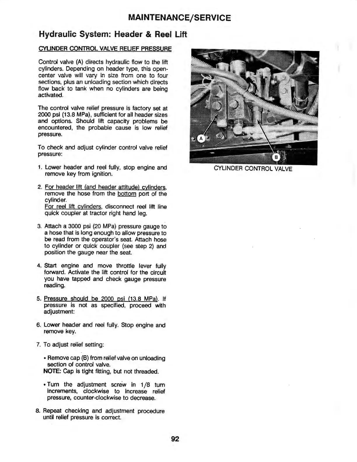
Control valve
(A
) directs hydraulic flow
to
the lift
cylinders. Depending on header type, this open-
center valve will vary in size from one
to
four
section
s,
pl
us an unloading section which directs
flow back
to
tank when no cylinders are being
activated.
The control valve relief pressure is factory set at
2000 psi
(13
.8
MPa)
, sufficient for all header sizes
and option
s.
Sh
ould lift capacity problems be
encountered, the probable cause
is
l
ow
relief
pressure.
To check and a
dj
ust cylinder
co
ntrol valve relief
pressure:
1.
Lower header and r
eel
fully, stop engine and
remove key from ignition.
2. For header lift (and header attitude) cylinders,
remove the hose from the bottom port of the
cylinder.
For reel lift cylinders, disconnect reel lift line
quick coupler at tractor right hand leg.
3. Attach a
3000
psi
(20
MPa)
pressure gauge to
a hose that is long enough
to
allow pressure to
be read from the operator's sea
t.
Attach hose
to
cylinder
or
quick coupler
(see
step
2)
and
position the gauge near the seat.
4.
Start engine and move throttle lever fully
forward. Activate the lift control for the circuit
you have tapped and check gauge pressure
reading.
s. Pressure should be
2000
psi
(13
.8
MPa)
. If
pressure is not as specified, proceed with
adjustment:
6. Lower header and
reel
fully. Stop engine and
remove key.
7.
To adjust relief
se
tt
ing:
• Remove cap
(B)
from relief valve on unloading
section
of
control valve.
NOTE: Cap is tight fitting, but not threaded.
• Tum the adjustment screw in 1 / 8
tum
increments, clockwise
to
increase relief
pressure, counter-clockwise
to
decrease.
8. Repeat checking and adjustment procedure
until relief pressure is correct.
92
CYLINDER CONTROL
VALVE