11,,
THIS
DRAWING
ANO
ALL
INFORMATION
THEREON
IS
THE
PROPERTY
OF
MacOon
lndumi"
Ltd.
IT
IS
LOANED
CONFIDENTIALLY
ANO
MUST
NOT
Bl:.
USED
IN
ANY
WAY
DETRIMENTAL
TO
OUR
INTEREST.
~
~
qoOD
,t151't"c..-10
NS
otJ...,Y
,..._
____________
--!
())
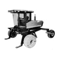
Two-Speed Control Linkage:
Assembly and Adjustment Instructions
·he
following procedures must be complete before beginning these instructions:
• Final Drive with
motor
and plntle arm installed and bolts tightened.
• Cab Installed.
• Cross shaft
at
rear
of
frame installed.
. a) Separate chain (A)
at
connecting link.
b) Install tonger length.of chain
at
forward hole of control arm (B) and shorter length
at
rear hole
of
control arm.
c)
Run
both chains
CNer
rollers (C) and let free ends hang down.
i.
Rotate cross shaft
(F)
counter-clockwise (as seen from left end) until crank arms
(G)
at both ends contact the lower
limit stops (H).
1.
On
both motors, move pintle arms
(K)
down
against an internal stop in the motor.
NOTE:
There
will
be
an audible
"clic~
when contact is made.
t On both sides:
a) Adjust length
of vertical control rod (M)
so
that hole in clevis (N) lines up with hole in bushing
at
pintle
arm
(K).
b) Connect clevis
to
plntle arm with bolt, slotted nut and cotter pin.
c) Tighten lock nut
at
rod end against ball joint
(L)
.
>. a, Jtate cross shaft
(F)
clockwise (as seen from left end) until crank arms
(G)
at
both ends contact the upper
limit stops (R).
b) On both sides,
tum
adjusting bolt
(P)
down until head
of
bolt contacts the arm.
c) Tum bolt
(P)
one-sixth
tum
further down, then
lock
the bolt position with nut.
NOTE: When turning nut
to
tock the position,
be
sure bolt does
not
tum.
5. a) Move control lever
(D)
in
cab
forward
so
that knob is approximately 480
mm
forward
of
rear
cab
window
(E).
b) Run the forward 0ong) chain under sprocket
(J) and connect
It
to
the rear (short) chain end.
b) Tighten the chain
by
moving one
or
both rollers
(C)
in slots, then tighten roller
to
secure the position.
NOTE:
Control lever
(D)
may move slightly
whUe
doing this.
No
correction is necessary.
7.
Move control lever (D) back and forth several times checking for proper function. The force required
to
move the
control lever
into
either end position should
be
between 6 and 20 lbs. (26 - 90 N).
If
not, repeat steps 4 and 5.
Make sure linkage
is
not obstructed
by
other machine components, (eg. lmproperty routed hoses).
NOTE: After removing
of any
of
these components,
or
loosening hardware which affects the adjustment, repeat the
above procedure.
DIMENSIONS
ARE:
MATERIAL
-----+-
-
-+---+---t----t
MILLIMETRES
-----+---+---+---t----1
UNLESS SPECIFIED
TOLERANCES ARE:
--
-•!:2
·X•i1
•0
-
·XX•
!0-25
ANGLES•
!1"
NAME
SPEC-
.
2..
SPEED
ASS'¼
AS$Y.
SCALI
-
TYPE
_.c;-41
CODE
CD
<..,J
--
-D-@
SERV N
"fl,\JC.TIONS
l428o
t#\Rt>
HWM
h\'1,'~
/4J(J2
MRS
HW'1
Fff-J9/
ti)
MocDon
lndust,ies
ltd.
PARTNo
44683
CHG.BY
Wmpeg.
Mcritoba
DATE
E.C.N
CKO.
BY
~
ct
0
z
:IE
a:
0
...