215626 20 Revision A
$
%
&
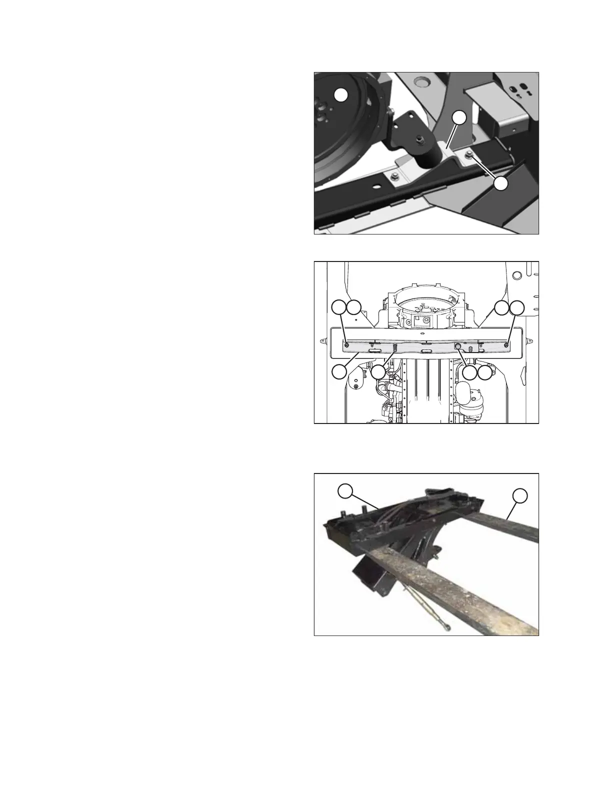
Figure 2.18: Front Engine Mounts
3. Remove outer bolt and nut (A) from front engine
mounts (B) on the left and right sides of engine (C). Retain
the nuts.
$
%
%
&
&
'
(
)
Figure 2.19: Linkage Support Installed
4. Mount linkage support (A) to the windrower frame with
two 1/2 in. x 2 3/4 in. long hex head bolts (B) with flat
washers under the bolt heads. Secure the bolts with
nuts (C).
NOTE:
These bolts replace the engine mount bolts removed in
Step 3, page 20.
5. From below the support, install 3/4 in. x 3 1/2 in. long hex
head bolt (D) with flat washer (E) under the bolt head.
6. Secure the bolt with a flat washer, a lock washer, and a nut
on the top side of the frame.
7. From above the support, install 3/4 in. x 5 1/2 in. long hex
head bolt (F) with a flat washer under the bolt head.
Do NOT install a nut on bolt (F).
$
%
Figure 2.20: DWA Linkage
8. Support linkage assembly (A) with a forklift.
IMPORTANT:
Make sure forks (B) of the forklift do not lift against the
cylinder fitting.
SETUP INSTRUCTIONS