Valve Clearance
Inspection / Adjust
A5.05. 01.01.01.00
1500
M20
en / 29.05.2000 IB021028 2/2
01
Ĺ
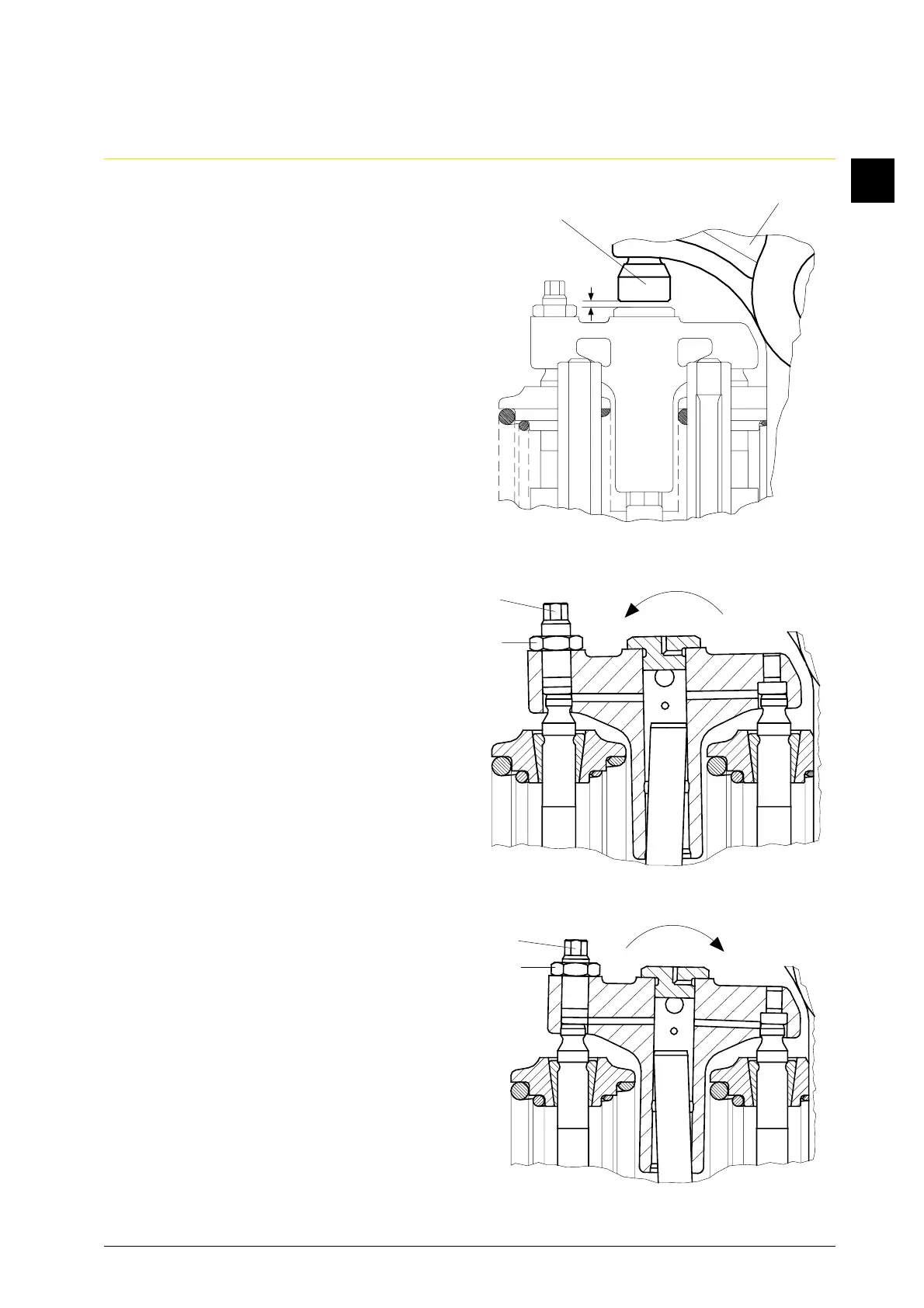
1.4 Adjust a sufficiently large clearance “s”
between the valve rocker (Fig. 1/1) and/
or valve bridge by folding back the
valve rocker (1) and/or by adjusting the
valve adjusting screw (2).
1.5 Loosen counternut (Fig. 2/3) and
unscrew the adjusting screw (4) until
there is sufficient clearance when the
valve bridge is tipped in the direction of
rotation “a”.
1.6 Tilt the valve bridge in the direction of
rotation “b” and screw the adjusting
screw (Fig. 3/4) into the valve bridge
until the valve bridge has contact at
both valves. Tighten counternut (3).
Note:
During tightening of the counternut, the
adjusting screw (4) turns back so far
that an equal gap between valve bridge
and both valves is obtained.
2. Adjust the valve clearance.
2.1 Measure the clearance (Fig. 1/S) by
means of a feeler gauge. Thereby, press
the pushrod down.
2.2 Correct clearance “s”.
2.2.1 Loosen counternut.
2.2.2 Turn the square of the valve adjusting
screw (2) until the prescribed clearance
is obtained.
2.2.3 Retighten the counternut to fix the
position of the adjusting screw.
2.2.4 Recheck the clearance after the
counternut is tightened.
Fig. 1
2
S
1
Fig. 2
4
3
a
Fig. 3
4
b
3