RPM Switch
Inspection / Adjust
A5.05. 11.05.01.01
7500
M20/M25/M32/M453C/M552C
en / 31.05.2000 IB021724 1/2
11
Ĺ
See also:
Spare parts list:
Time requirement: 1 Pers./ 1,00 h
Personnel qualification: E-specialist
---------------------------------------------------------------------------------------------------------------------
Operating medium: Heavy fuel and distillate fuel
Inspection:
Check the function of the rpm switches every 7,500 operating hours.
Note:
The engine speed must be constant whilst testing.
Sequence of operations:
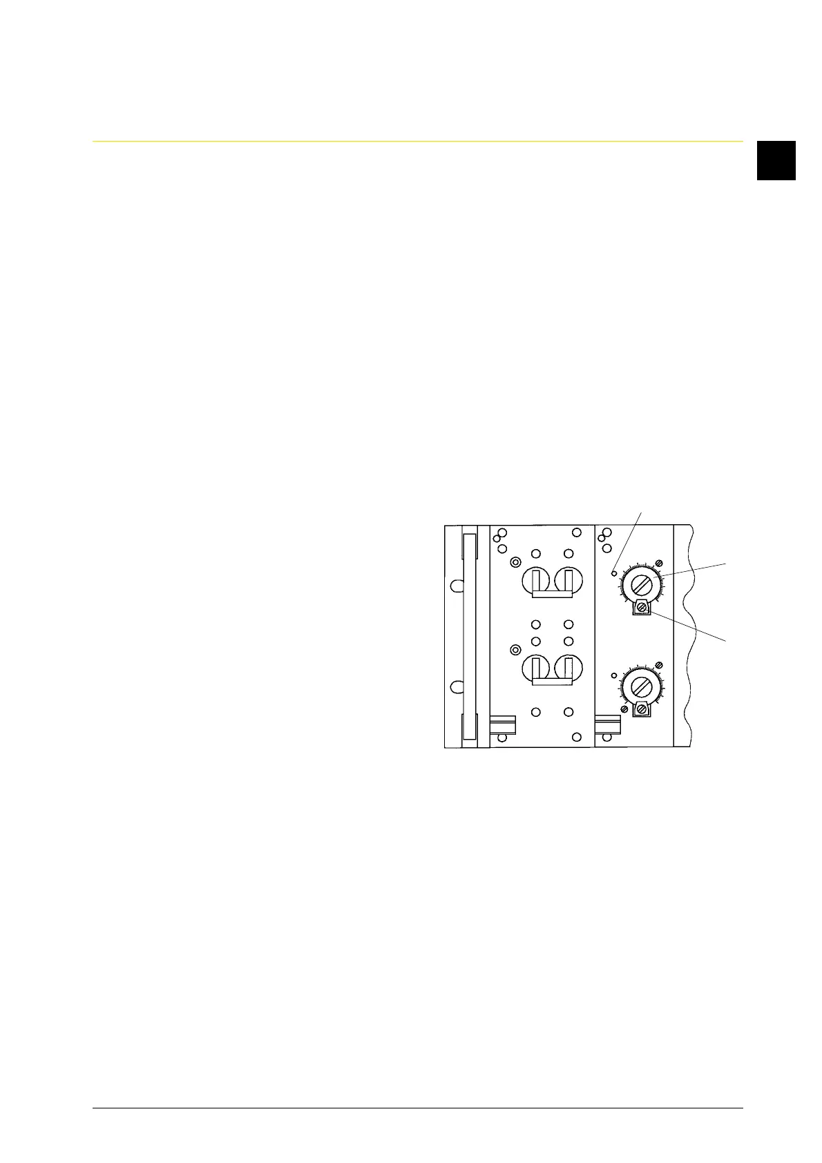
1. Note the rpm switch point setting.
Loosen the pointer locking plate (2) and
set the pointer (1) at the highest engine
speed.
The output relay on the plug-in card
must switch and the luminous diode (3)
on the dial will go out (Fig. 1).
2. Turn the pointer carefully to the left
towards 0 rpm. When reaching the
engine speed, the output relay will
switch and the diode on the dial must
light up (switch hysteresis ± 25 rpm).
3. Set the pointer again at the original rpm
switch point and lock it.
If the rpm switch does not work,
proceed as follows in order to locate
the defect:
4. The automatic cut-out F 1.1 and F 2.1 on the plug-in card A1 in the rpm switch installation
must be switched on.
At constant speed and with the setting as under point 1, continue as follows:
5. Voltage check at the plug-in socket contacts of the plug-in frame.
5.1 Supply (24 V DC at contact z16 and z20, contact z20 positive).
A 1
F 1.1
F 2.1
A 2
3
1
2
Ĺ
Ĺ
Fig. 1