Valve Seat Ring
Repair / Checking
A5.05. 01.08.02.01
M20
en / 15.03.2001 IB023062 4/5
01
Ĺ
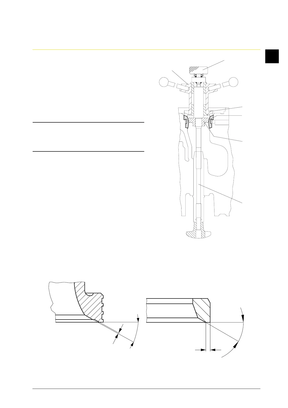
3.1.3 Place cutter head (Fig. 6/2) on greased
mandrel, screw in knurled thumb screw
(1), until resistance becomes
noticeable.
3.1.4 Rotate valve seat (clockwise) uniformly
and slowly and remill the seat in one
operation pass. The cutting of the
cutters must be noticeable. Set the
contact pressure by touch.
Attention:
The machine will rattle when the
contact pressure is too low and/or the
cutting speed is too high.
3.1.5 Prior to finishing the cutting process,
slowly unscrew the knurled thumb
screw (1) and simultaneously rotate the
cutter head.
3.1.6 Max. permissible dimension for rewor-
king:
Exhaust valve (Fig. 7):
The shoulder "y" must still remain di-
stinct.
Inlet valve (Fig. 7a):
The dimension for "z" must not drop
below the minimum dimension of 1
mm due to the reworking.
1
2
3
4
5
W2
Fig. 6
z
y
20
° 5' +
5
'
3
0° 5' +
5
'
Fig. 7
Fig. 7a