Cylinder Head
Repair / Reassembly
A5.05. 01.11.01.00
M20
en / 16.09.1997 IB001353 3/5
01
Ĺ
Note:
Insert all O-rings with vaseline or green grease soap untwisted into grooves.
4. Carefully place cylinder head with cylinder head lifting device (W9) and lifting gear onto
cooling water distributor housing. Avoid jamming of cooling water transition on pushrod
passage.Insert pushrods into cylinder head. Observe fixing pin in the cooling water
distributor ring.
5. Insert new seal (Fig. 1/7) for exhaust flange and align cylinder head. Lubricate screws for
exhaust pipe with “Dag S-5080” high-temperature thread paste and screw in loosely with
resilient sleeves.
6. Tighten the four cylinder head screws
together with the hydr. tightening
device.
Attention:
Max. lift of 5 mm must not be
exceeded.
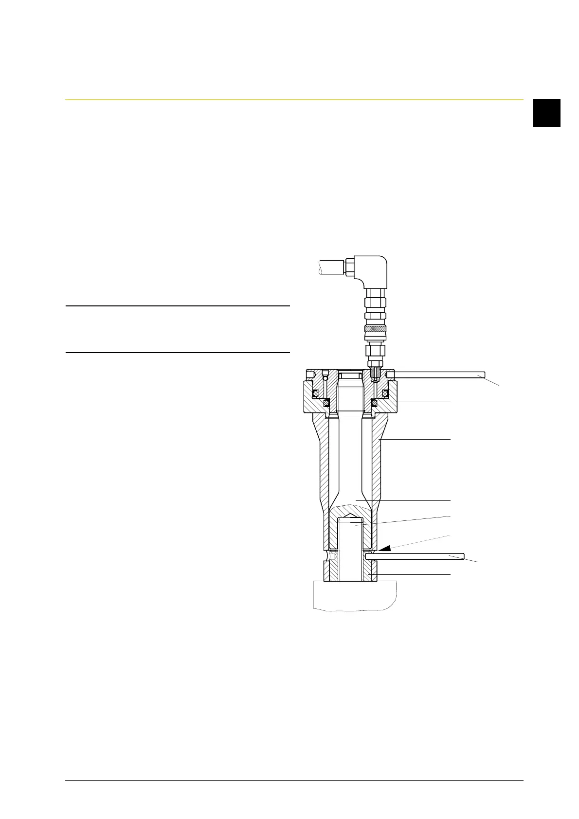
6.1 Tighten round nuts (Fig. 2/12) with pin
(W8) hand-tight.
6.2 Screw spacer (W7) onto cylinder head
screw (11).
6.3 Place bearing ring (W6) over round nut
(12), thereby, make sure the slots (13)
are easily accessible.
W8
W4
W6
W7
11
13
W8
12
Fig. 2