Crank Web Deflection
Inspection / Measuring
A5.05. 02.02.01.00
M20
en / 13.06.1997 IB001439 2/4
02
Ĺ
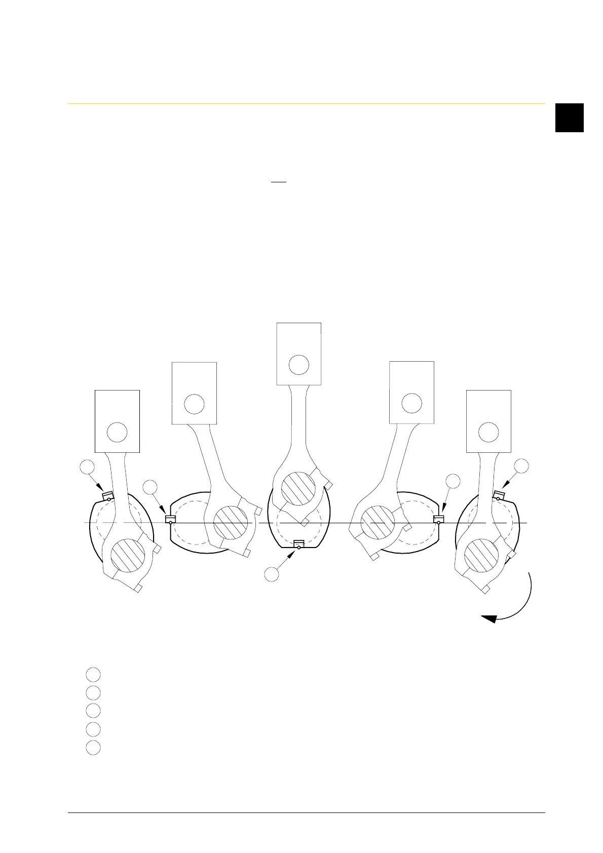
Sequence of operations:
1. Bar crank pin from BDC in direction of exhaust side to such an extent that the dial gauge
can be applied between the crank webs at the point farthest away from the crank pin and
the connectiong rod just passes by the dial gauge (Fig. 2/1st measuring point).
Where punch holes are found, do not place the measuring tips on the centring marks, the
purpose of the latter is only to indicate the space in which to use the measuring tips.
2. Adjust the value of scale “20” to the pointer: 1st measuring point (initial point).
3. Bar the crankshaft so that the crank pin turns in direction of the exhaust side and the dial
gauge towards the camshaft side.
4. Continually watch the gauge and read off the values in the measuring points 2 - 5. If before
or behind a measuring point a higher value than at the prescribed measuring point itself is
read, this value has to be recorded.
= 1st measuring point (initial point)
= 2nd measuring point (pin on exhaust side)
= 3rd measuring point (pin in TDC)
= 4th measuring point (pin on camshaft side)
= 5th measuring point (pin in BDC camshaft side)
Fig. 2
5
3
4
2
1
1
2
3
4
5