Main Bearings
Inspection / Disassembly
A5.05. 02.05.01.01
15000, 30000
M20
en / 30.05.2000 IB021418 2/5
02
Ĺ
Note:
The bearing caps and bearing shells are marked continuously on the camshaft side starting
from the clutch side according to which cylinder they belong and must not be exchanged.
New parts are to be marked correspondingly.
Even within the prescribed interval, the main bearings are to be removed, checked and
measured if:
Substructure deformations and/or crank web deflection changes after crashes appear and/
or if the connecting rod bearings are found in a poor condition.
Sequence of operations:
1. Remove main bearing.
1.1 Open driving room covers on camshaft and exhaust side and turn crankshaft into favorable
position for removing.
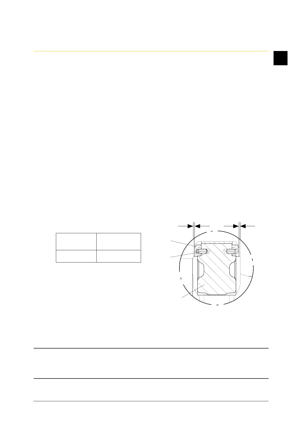
1.2 Measure axial play “s” by the locating bearing (Fig. 1).
1.2.1 Place gage with magnetic holder on flywheel set and align at the cylinder block and
crankcase.
1.2.2 Offset crankshaft axially, until bearing is on one side. Set gage to “zero”. Shift crankshaft in
the opposite direction and read off axial clearance “s” at gage.
1.2.3 Axial play “s”:
s = s
1
+ s
2
New clearance Limit clearance
mm mm
0.23 - 0.4 0.6
If the limiting clearance is exceeded,
renew the stop disk segments and
bearing shells in pairs.
Note:
Lower stop disk halves (Fig. 1/1) are
pinned with clamping pins (2) at the
bearing cap (3).
Attention:
It is imperative to mark the stop disks before a possible disassembly for checking
purposes, so that they cannot be interchanged.
Afterwards re-assemble them immediately!
s
1
s
2
Fig. 1
3
2
1