Main Bearings
Inspection / Disassembly
A5.05. 02.05.01.01
15000, 30000
M20
en / 30.05.2000 IB021418 4/5
02
Ĺ
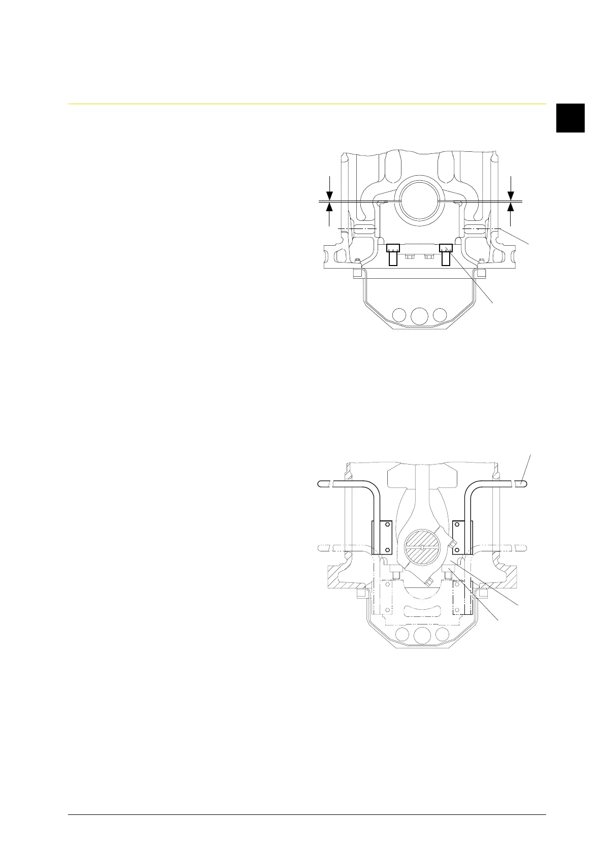
1.4 Measure clearance.
1.4.1 Remove hexagon screws (Fig. 4/11) of
the respective main bearing on exhaust
and camshaft side.
1.4.2 Hydraulically loosen both round nuts
(12) in accordance with sequence of
operations 1.3.
1.4.3 Relieve hydr. removal equipment and
remove.
1.4.4 Tighten round nuts in turn by hand and
uniformly, until the parting faces of the
bearing shells just come into contact
with each other.
1.4.5 Measure clearance “K” between
cylinder block and crankcase and
bearing cap on exhaust and camshaft
side with feeler gage and add the two
measured values.
K = K
A
+ K
S
Clearance “K” Operating limit value
mm mm
0.50 - 0.80 0.4
1.5 Screw lowering device (Fig. 5/W6) onto
bearing cap (21) on exhaust and
camshaft side.
1.6 Twist down round nuts (12) uniformly
from bearing bolts and lower bearing
cap carefully. Bearing cap is suspended
on lowering device in the cylinder
block and crankcase.
1.7 Remove lower bearing shell from
bearing cap.
Fig. 4
12
K
A
11
K
S
W6
21
12
Fig. 5