Governor Drive
Inspection / Disassembly and reassembly
A5.05. 04.08.03.00
15000
M20
en / 05.06.2000 IB022022 2/3
04
Ĺ
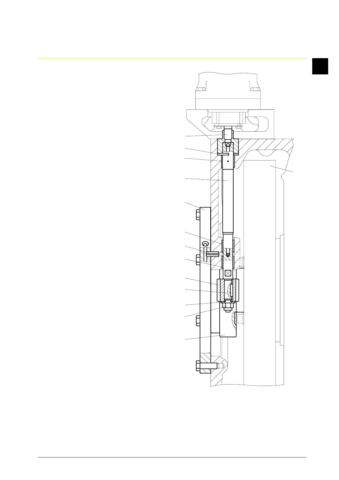
1.4 Loosen and remove the cover (Fig. 2/11)
at the gear housing, taking care of the
dowel pin (12). Check the oil lubricating
hole.
1.5 Loosen the hexagon screws at
the helical gear wheel (13) and remove
the helical gear wheel (13) from
the camshaft gear (14).
1.6 Release the castellated nut (15) and
unscrew it with the conical spring
washer (16) from the governor drive
shaft (17).
1.7 Pull off the helical gear wheel (18) from
the governor drive shaft (17), taking
care of the parallel key (19).
1.8 Check the tooth surfaces of the helical
gear wheels (13 and 18) for wear
(pitting, cross bearing, disintegrations).
1.9 Lift the governor drive shaft (17) out of
the cylinder block and crankcase and
check for wear.
1.10 Remove the serration from the go-
vernor drive shaft (17) and check the
shaft (20) for wear.
1.11 Check the washer (21) for wear and
renew it if necessary.
1.12 Check all oil lubricating holes for the
lubrication of the governor drive shaft
(17) and helical gear wheels (13 and 18)
for flow through.
Note:
The governor drive shaft (17) is
installed in the top and lower part of
the cylinder frame. If required,
the bushes (22 and 23) are to be driven
out with a suitable mandrel from
the cylinder block and crankcase and
renewed.
Fig. 2
20
14
21
22
17
11
23
12
23
18
19
16
15
13