Injection Pump
Repair / Disassembly and reassembly
A5.05. 07.02.01.01
M20
en / 16.06.1997 IB003956 3/3
07
Ĺ
2.2 Replace the O-rings on the lower spring plate (Fig. 3/22) and the connections for the fuel
manifold and collector (24).
2.3 Place the injection pump above the fastening screws.
2.4 Lubricate threads and contact surfaces of nuts (Fig. 2/14) with Molykote paste
“G-Rapid Plus” and pull the injection pump into place by tightening the nuts uniformly.
ĭ Safety note:
Caution! Spring tension of the injection pump drive interacts with the injection pump.
2.5 Tighten nuts (14) with a torque of
M = 50 Nm.
2.6 Connect lube oil lines (Fig. 1/1) to the
injection pump and screw on holder for
stop cylinder (3).
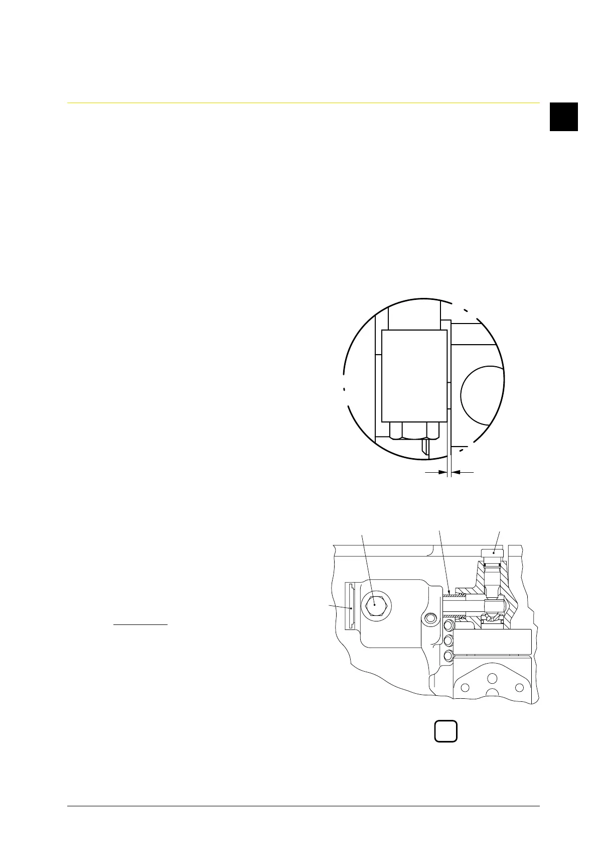
2.7 Link regulating shaft with control rack
(2) of the injection pump. Observe
clearance “s” of 0.5 mm between
articulated lever and control rack
(Fig. 1/X) and ensure freedom of motion
of the accelerator control linkage.
2.8 Slide transverse pressure piece of the
injection pressure line with cover
(Fig. 4/12) in reverse disassembly
direction into cylinder cover and
injection pump. First tighten the thrust
screw (11a) and then thrust screw (11b)
with a torque of
M = 85 Nm.
Slide sleeve (13) to the right into
injection pump.
2.9 Mount the fuel manifold and collector
(07.1
5.01.nn).
2.10 Vent fuel system with backing pump.
X
s
4
13 11a11b
12