Centrifugal Cooling Water Pump
Maintenance / Disassembly and reassembly
A5.05. 09.07.01.01
15000
M20
en / 06.06.2000 IB022224 3/3
09
Ĺ
.
3.4 Before mounting the gear wheel (2) (Fig. 1/X), check contact reflection between gear wheel
cone and shaft cone by spot-grinding. A uniformly distributed contact reflection must be
offset to the thicker end.
3.5 Heat up the gear wheel (2) to approx. 150 °C and push it up to the stop on the shaft cone.
3.6 Grease the thread and contact surface of the hexagon screw (3) and the washer (4) with
Molykote paste “G-Rapid Plus” and tighten it with a torque of
M = 60 Nm.
3.7 Insert the cooling water pump (1) with the gear wheel (2) carefully into the cylinder block
and crankcase (the tooth surfaces of the driving toothed wheels must mesh into each
other) and mount it at the pump carrier plate with sealing compound
(Backlash = 0.2 mm - 0.5 mm).
3.8 Mount the pipes and refill and vent the cooling water system.
3.9 Check the tightness.
3.10 Check the lube oil supply of the gear wheels.
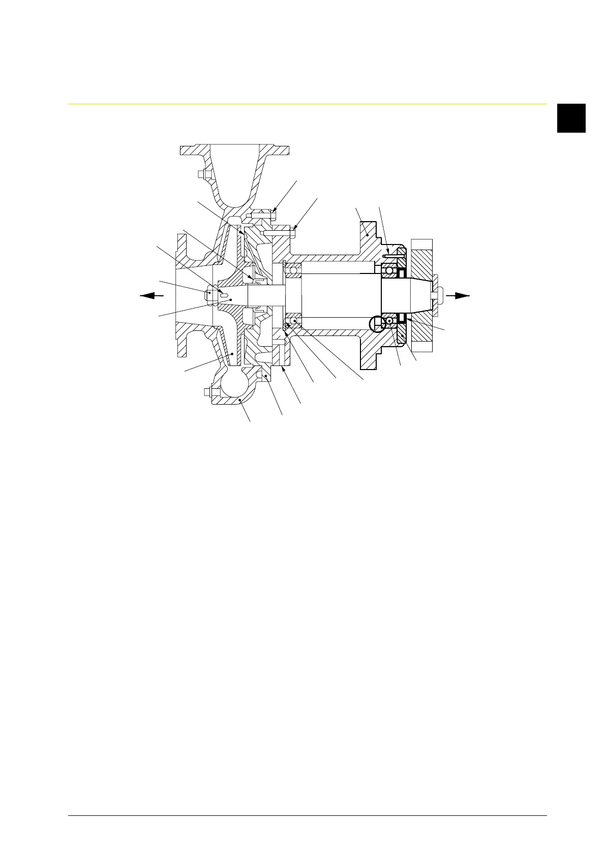
Fig. 2
19
28
27
Z
20
22
22
11
15
16
17
24
25
21
14
12
5
13
26
18
Y X