Pressure Switches
Inspection / Adjust
A5.05. 11.01.02.01
3750
M20-M601C
en / 31.05.2000 IB021686 3/3
11
Ĺ
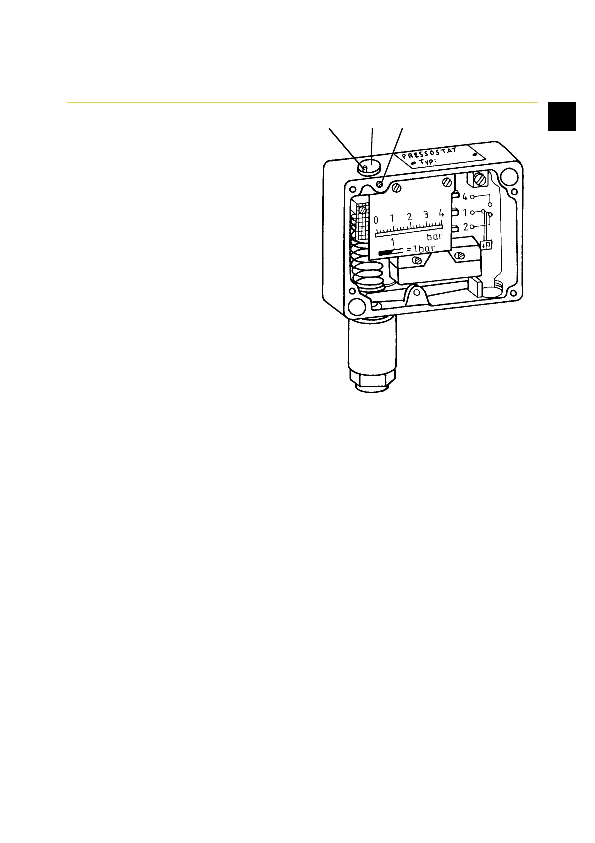
3. Correction of the adjustment (Perfor-
mance with fixed switch difference)
(Fig. 3)
Note:
The scale accuracy is ± 2 % of the span.
The instrument is individually
calibrated (1 - 2 on) so that no gauge
inspection is necessary.
3.1 Remove the case cover by loosening
the 4 locking screws.
3.2 Connect terminal (1 + 4) via cable with
the adjusting device.
3.3 Loosen the stop screw (A).
3.4 Remove the cover aside by loosening
the locking screw (B).
3.5 Set the upper or lower switching point
(differential pressure switch) by means
of the range spindle (C).
The lower or upper switching point
(differential pressure switch) results in
the fixed switching difference.
3.6 Tighten stop screw (A).
4. Removal of the adjusting device
4.1 Loosen the cable connection
(terminal 1 + 4).
4.2 Loosen the connection hose of the
adjusting device screw on the union
nuts with plug (Fig. 1/2).
4.3 Fit the cover.
4.4 Tighten the cover of the range spindle.
4.5 Mark or lead the impected or corrected
pressure switches.
•
Fig. 3
BCA