Pressure Switches
Inspection / Adjust
A5.05. 11.01.03.00
3750
M20
en / 31.05.2000 IB021766 2/3
11
Ĺ
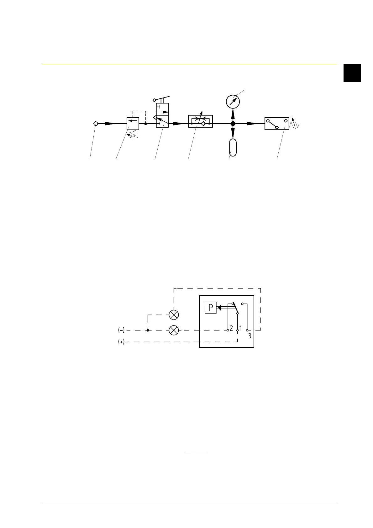
1.3 Pneumatic connection (Fig. 2)
10 Compressed air flange > 16 bar
11 Pressure reducer
12 Stop valve
13 One-way restrictor
14 Volume 1 l
15 Precision manometer
16 Pressure switch
1.4 Electric connection (Fig. 3)
Connect terminals 1, 2, 3 in the appliance plug.
2. Inspection
2.1 Vent pressure switch via adjusting device.
2.2 Check switching point via the precision manometer of the setting equipment and
test lamps.
2.3 Gradually vent the pressure switch, thereby observe switching point on the precision ma-
nometer the adjusting device and test lamp (Check the indicated switching differential in
accordance with measuring point list in Book C).
10 11 12 13 14 16
Fig. 2
15
Fig. 3