Vibration Damper
Maintenance / Disassembly and reassembly
A5.05. 12.04.01.03
30000
M20
en / 06.06.2000 IB022217 2/2
12
Ĺ
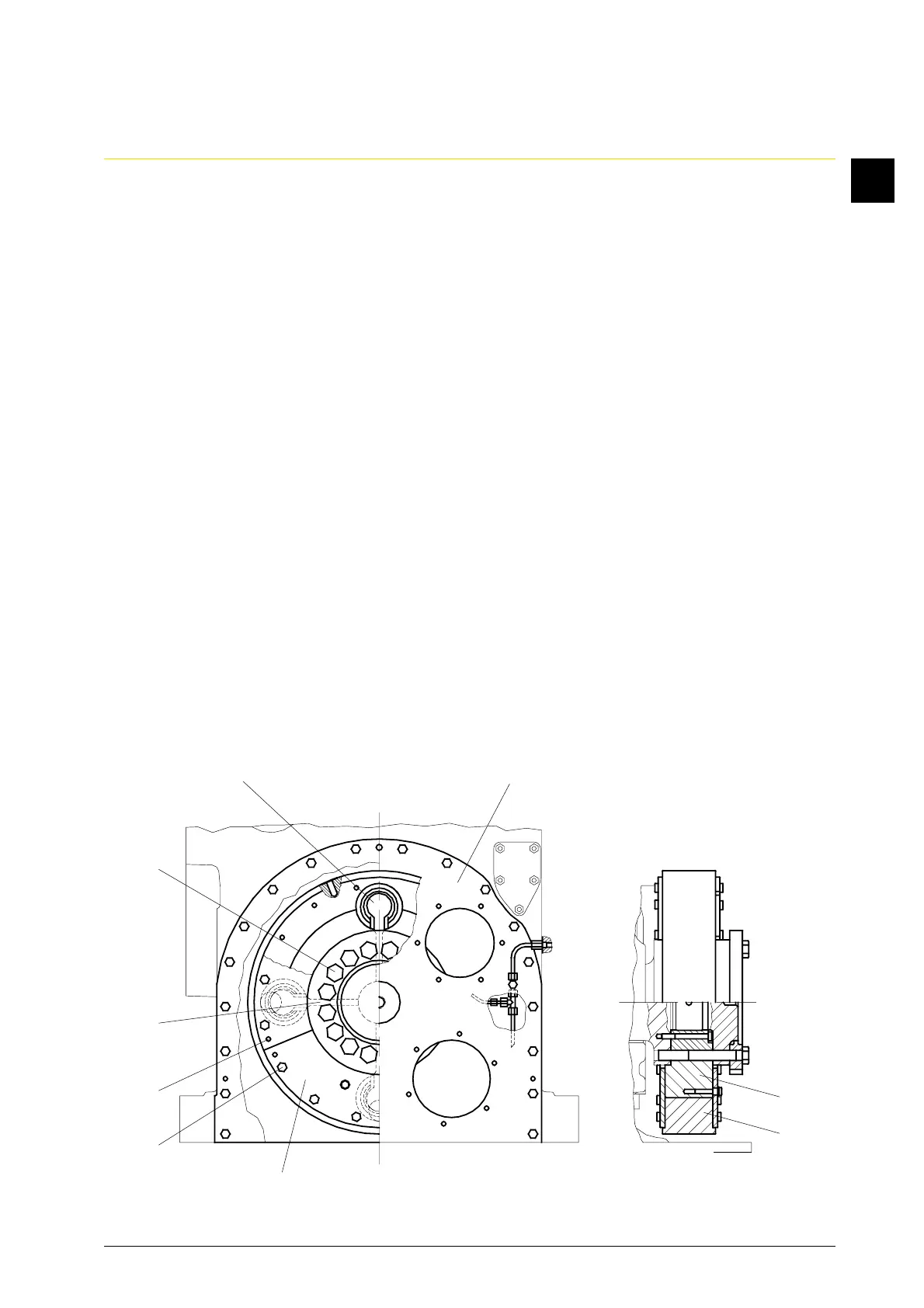
1.4.2 Telescope out spring assemblies (Fig. 1/9).
•Inspect springs for grooves and cracks.
•If individual springs show grooves or are broken, replace spring assembly (9) completely.
1.5 Clean the vibration damper thoroughly, check oil bores for free passage with wire.
1.6 Inspect the flywheel rim (7) on carrier (8) for easy turning.
1.7 Check the spring assemblies (9) for completeness.
1.8 Turn the flywheel rim (7) and the carrier (8) in the marked position, apply a thin film of
Molykote paste “G-Rapid Plus” to the springs and insert them into the damper. For this
purpose, slightly squeeze spring assemblies (9) together with a screw clamp.
2. Reassembly
2.1 The remaining assembly is carried out under observation of markings in reverse
disassembly order. Tightening torques of the screws:
M 12 = 60 Nm
M 8 = 25 Nm
2.2 Coat thread and screw head rest with Molykote paste “G-Rapid Plus”.
2.3 Secure all screws/nuts with wire/split pins or cup springs acc. to design.
2.4 Mount pump carrier plate (3) mit sealing compound on cylinder crankcase.
2.5 Check lube oil supply of the toothed wheels.
Fig. 1
9
1
2
6
5
4
8
7
3