Drive lever control unit
41
Read this manual carefully before starting any work!
This is particularly applicable to the chapter “General Safety Instructions”
and the respective safety instructions in the chapters.
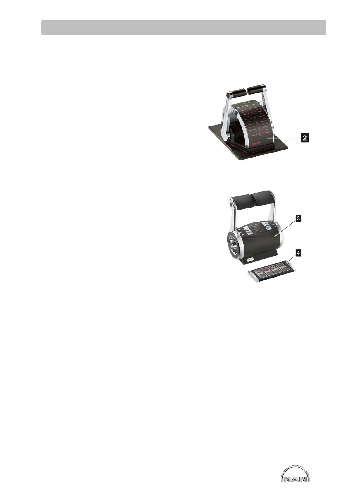
7.1.1 Components of the internal drive lever control unit
Termination at the end of the bus on the drive
lever
Selection of the utilized drive lever (2, 3) and
control strip (4) (examples) will also be
implemented on behalf of the customer by MAN
together with the company Aventics.
Various versions in combination with control strips,
displays and CAN modules are possible but must
always be coordinated on a project-related basis.