Installation
59
Read this manual carefully before starting any work!
This is particularly applicable to the chapter “General Safety Instructions”
and the respective safety instructions in the chapters.
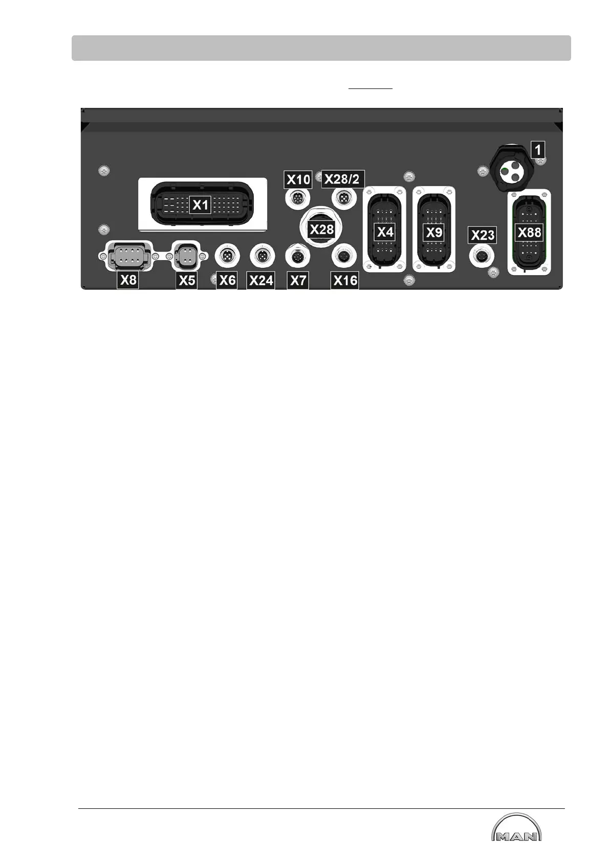
8.4 Overview of plugs at the electronics box without acceptance
Plug assignment (E-box with/without display)
X1 Connection of engine - E-box alarm system
X4 Connection plug for shipyard-side wiring.
X5 Reduction command to adjacent engine (mutual reduction)
X6 CAN connection of the display instruments/displays
X7 Reserve
X8 Gearbox feedback signals
X9 Connection for external drive lever control
X10 Connection for diagnostics software (only for MAN Service).
X16 Connection of override button for alarm system (optional)
X23 Without function, only reserve
X24 Without function, only reserve
X28 Ethernet temporary
X28/2 Ethernet permanent M12 interface
Note: Do not use connections at the same time, either X28 or X28/2
X88 Reserve/partial access to internal drive lever control unit; not on connector board (optional)
(1) PG gland: Cable conduit for internal drive lever control unit
Connecting cables, see page 116.