Drive lever control unit
42
Read this manual carefully before starting any work!
This is particularly applicable to the chapter “General Safety Instructions”
and the respective safety instructions in the chapters.
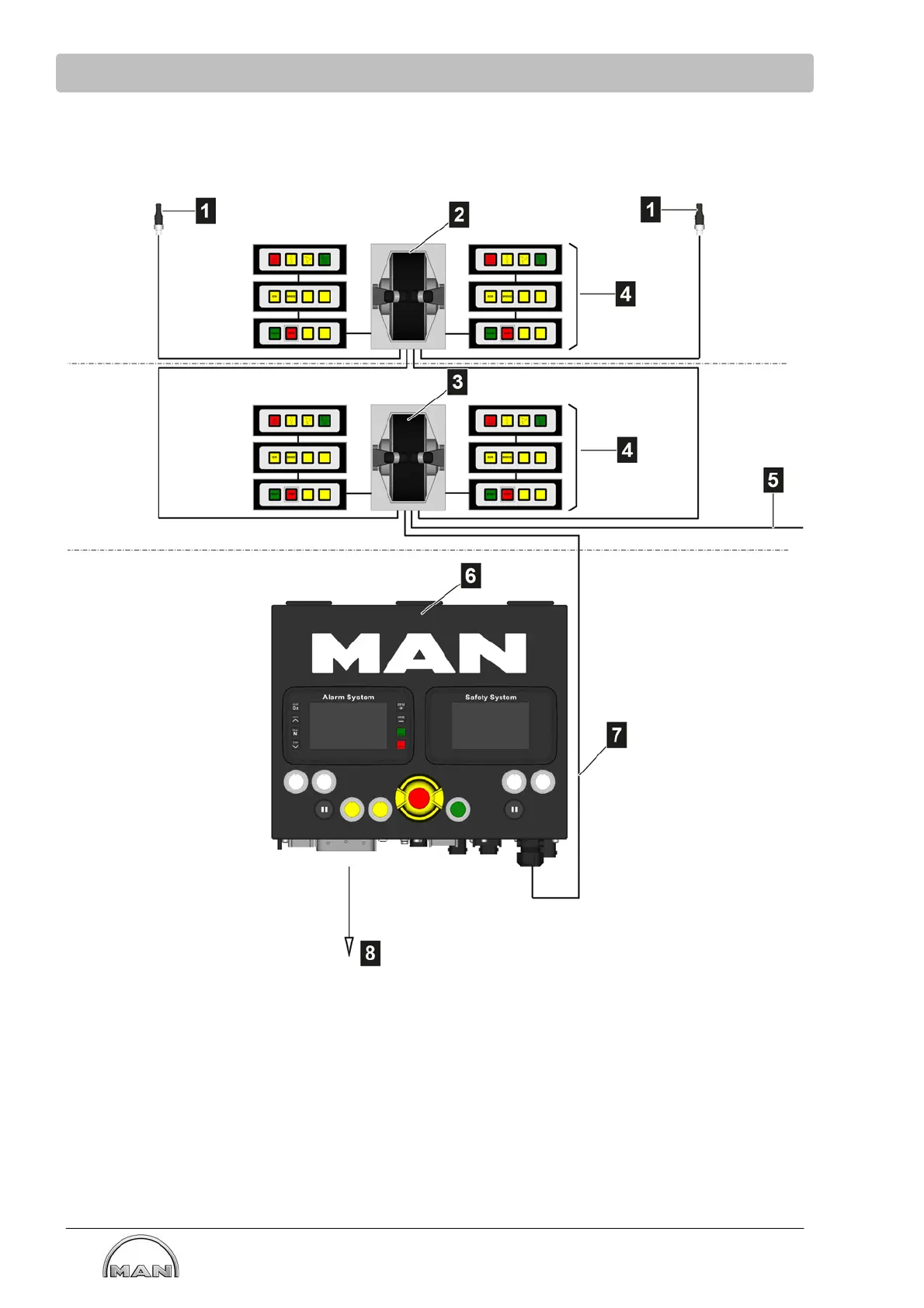
7.1.2 Wiring of the internal drive lever control unit
Example: E-box with acceptance and 2 operator's stands
Bridge
Engine
control room
(1) Terminating resistor
(2) Drive lever, bridge
(3) Drive lever, engine control room
(4) Control strip
(5) Second engine
(6) Electronics box
(7) Cable conduit for internal drive lever
control unit
(8) Voltage supply
Cross-communication with the second engine is not available for the E-box with acceptance.