Do you have a question about the Man iSea and is the answer not in the manual?
General information about the operating instructions and MAN's obligations.
Information on copyright, trademarks, and proprietary rights.
Importance of safety regulations and preparedness for hazards.
Conditions for lodging claims for material defects.
Explanation of warning icons (DANGER, WARNING, CAUTION, NOTICE) and symbols.
Safety instructions for planning and operation.
Guidelines for the correct and intended use of MAN marine diesel engines.
Rules regarding modifications to the engine and aftertreatment system.
Qualifications, training, and authorization for personnel.
Essential personal protective equipment (PPE) for safe operation.
Electrical hazards, moving components, flying debris.
Requirements for safety equipment, including emergency stop functionality.
Procedure for daily functional testing of the emergency stop.
Preventive measures and actions in case of accidents.
Explanation of important safety signs and symbols.
Guidelines for protecting the environment when handling service products.
Key development guidelines and principles for system safety.
Scope of the system, including engine and propulsion train.
System overview for non-classified applications.
System overview for classified applications.
Conditions for reverse gearbox function and consequences of non-compliance.
Diagram illustrating the classified system overview.
Diagram illustrating the non-classified system overview.
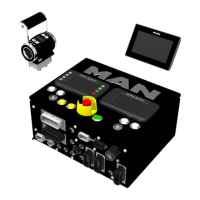
Description of different versions of the electronics box (E-box).
Details and technical data for the E-box without acceptance.
Instructions on how to open and close the E-box.
Detailed description of the components within the electronics box.
Installation and function of the internal drive lever control unit MPC.
Description and function of motherboards within the E-box.
Configuration details for jumpers and switches on the MCS motherboard.
Configuration details for jumpers and switches on the MCS-SU motherboard.
Function and logic of the MCS and MCS-SU control units.
Role and installation of the connector board in the E-box.
Details on the internal drive lever control unit (MPC).
Components of the internal drive lever control unit.
Wiring diagrams for the internal drive lever control unit.
Special functions and signals on plug X88 for internal drive lever control.
Details on the external drive lever control unit and its connection.
Pin assignment and connection details for plug X9.
Options for powering the drive lever control unit.
How to use speed signals for engine synchronization.
Functionality and requirements for start interlock.
Physical dimensions of the drive lever unit.
Safety precautions for engine room entry and installation personnel.
Procedures and safety warnings for installing the E-box.
Identification and assignment of plugs on the E-box (classified).
Identification and assignment of plugs on the E-box (non-classified).
Instructions for connecting the E-box to the engine.
Installation guidelines and dimensions for the bridge display.
Details of connections for the touch display.
Explanation of keyboard functions on the E-box (classified).
Overview of the non-classified electronic box.
Steps for starting and operating the engine from the engine room.
Procedures for operating the engine from a remote operator's stand.
Proper procedure for switching off the engine and system.
Guidelines for using the engine emergency stop button.
Explanation of keyboard functions on the engine room display.
Controlling the engine and gearbox locally via display buttons.
Overview of the engine room display menus and functions.
Description of the main menu and available operating values.
Display of fuel consumption related data.
Configuration options for language, units, display settings, etc.
Settings for idle speed and intermediate speed control.
Functionality and features of the bridge display.
Configuration and commissioning options for the touch display.
Overview of the main menu structure for the bridge display.
Information on warning, alarm, and signal error messages.
How to acknowledge alarms on non-classified systems.
How to acknowledge alarms on classified systems.
Detailed explanation of display settings like language, units, and modes.
Accessing service-related values and status displays.
Detailed output of control unit error memory for service engineers.
Configuration of digital inputs and outputs for the system.
Display of fuel consumption and engine operating hours.
Functionality of the video page for monitoring the engine room.
Functionality and activation of the emergency drive mode.
Parametrization and operation of the engine start/stop function.
Information on the MAN aftertreatment system and emissions monitoring.
Function of the Marine request system for NOx emissions monitoring.
Compliance with U.S. Tier 4 Marine emissions requirements.
Retrieving and storing emissions-related warnings and alarms.
Procedure for accessing and printing emissions history data.
Instructions for wiring the bridge display to the E-box.
Interface definition and components of the shipyard plug X4.
Methods for connecting start and stop apparatus for non-classified systems.
Wiring instructions for connecting emergency stop buttons.
Connecting an acoustic warning apparatus (buzzer/horn).
Purpose and function of the override system.
Installation of the override button and necessary data set adjustment.
Wiring connections for the override button to the E-box.
Example of override function using coolant temperature.
Description of the Engine Operation Panel EOP.
General functions of the Engine Operation Panel EOP.
Wiring details for the Engine Operation Panel EOP.
Installation procedures for the Engine Operation Panel EOP.
Description of the Engine Operation Panel EOP D.
General functions of the Engine Operation Panel EOP D.
Installation procedures for the Engine Operation Panel EOP D.
Connecting cables for Engine Operation Panels EOP and EOP D.
Dimensions and layout of the Engine Operation Panel EOP.
Dimensions and layout of the Engine Operation Panel EOP D.
Connecting cable specifications for bridge display A.
Connecting cable specifications for bridge display B.
Connecting cable specifications for bridge display C.
Connecting cable specifications for X4 E-box to ship.
Connecting cable specifications for X5 E-box to E-box.
Connecting cable specifications for X7 start-stop unit to E-box.
Connecting cable specifications for X8 E-box gearbox feedback.
Connecting cable specifications for X9 E-box to external drive lever.
Connecting cable specifications for X17 E-box local/remote display.
Connecting cable specifications for X21 E-box to external alarm system.
Connecting cable specifications for X41 E-box to external safety system.
Connecting cable specifications for X88 E-box gearbox function.
Steps for parametrizing the start/stop function via the touch display.
Configuring available start/stop stands within the system.
Assigning start/stop stands to specific displays.
Troubleshooting common error messages related to start/stop configuration.
Steps for parametrizing the emergency drive function.
Configuring available emergency operator stands in the system.
Assigning operator stands to specific displays for emergency operation.
Troubleshooting common error messages related to emergency drive configuration.
Interface description for X4 in classified applications.
Interface description for X8 in classified applications.
Interface description for X9 in classified applications.
Interface description for X17 in classified applications.
Interface description for X21 in classified applications.
Interface description for X41 in classified applications.
Interface description for X4 in non-classified applications.
Interface description for X8 in non-classified applications.
Interface description for X9 in non-classified applications.
General guidelines for CAN-2 interface on the bridge display.
Detailed description of the Ship-CAN interface (CAN-2).
Technical details of the EEC1 message.
Technical details of the EEC2 message.
Technical details of Turbocharger Info 4 message.
Technical details of Turbocharger Info 5 message.
Engine temperature data transmitted via CAN-2.
Fluid level and pressure data transmitted via CAN-2.
Intake and exhaust condition data transmitted via CAN-2.
Engine electrical power data transmitted via CAN-2.
Exhaust fluid tank data transmitted via CAN-2.
Transmission fluid data transmitted via CAN-2.
Time and date information transmitted via CAN-2.
Engine operating hours data transmitted via CAN-2.
Fuel economy data transmitted via CAN-2.
Fuel consumption data transmitted via CAN-2.
Aftertreatment SCR service information transmitted via CAN-2.
Auxiliary MAN Engine data transmitted via CAN-2.
DM_1_MAN-Engine message details for CAN-2 interface.
Example of deciphering DM1 messages from CAN-2 display.
List of abbreviations used in the manual.
| Brand | Man |
|---|---|
| Model | iSea |
| Category | Marine Equipment |
| Language | English |