Design and function
37
Read this manual carefully before starting any work!
This is particularly applicable to the chapter “General Safety Instructions”
and the respective safety instructions in the chapters.
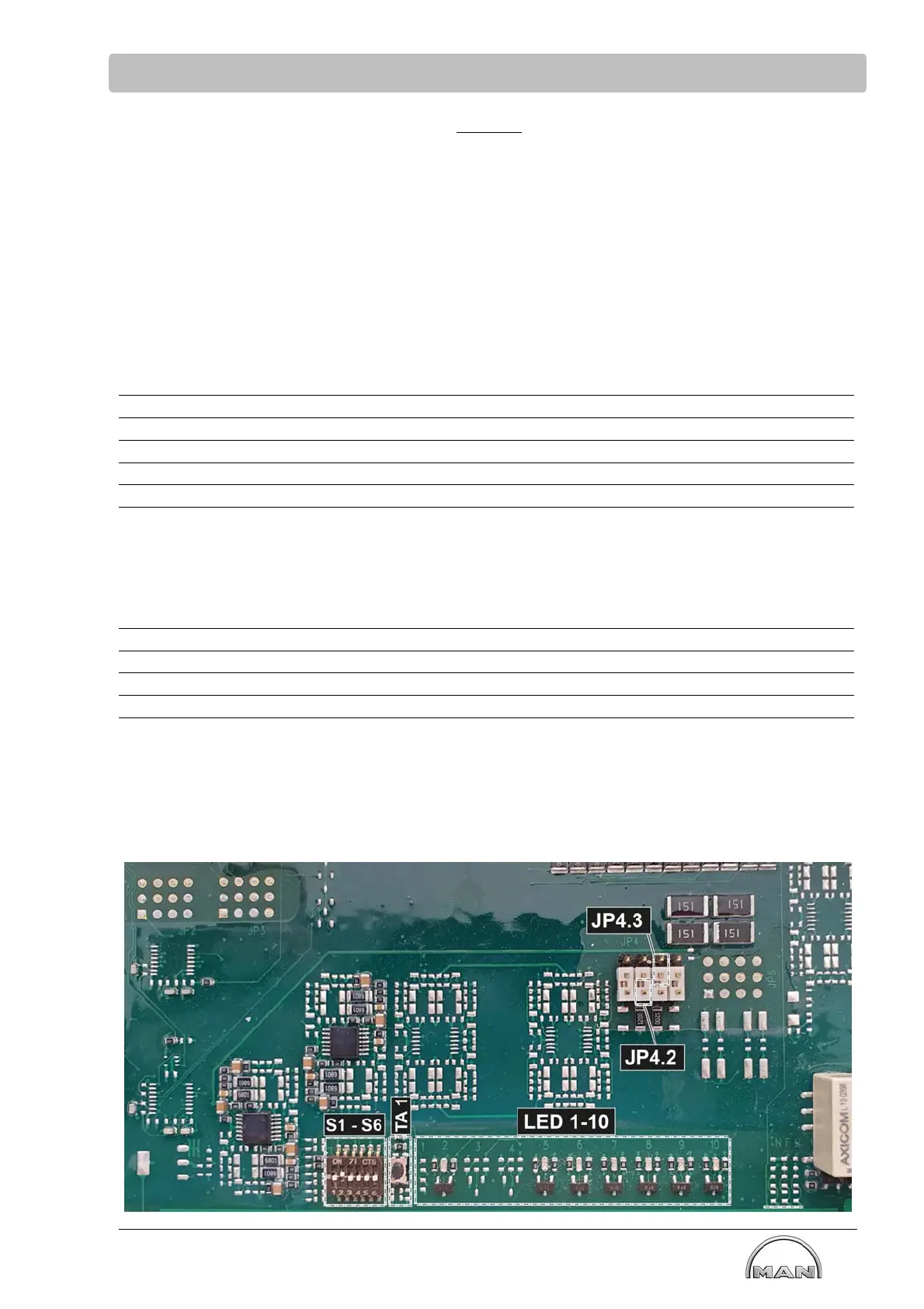
Jumper and switch position on motherboard MCS- SU
Default
JP Function
can be found
adjacent to bore State Pin
Jumper
position
4.2 CAN02 bus (monitoring) in MCS terminating
resistor active or not active
Center/right CAN disconnected 1-2 bottom
4.3 CAN03 bus (UDS) in MCS terminating
resistor active or not active
Center/right CAN not terminated 2-3 top
NOTE at JP4.3:
Delivery state = bottom → JP4.3 must be switched to „top“
Default
Switch Function To be found State Pin
Switch
position
S1
S2
S3 Test only: Overspeed test active or not active DIP switch Test not active Switch OFF
S4
S5
S6
TA1 Horn Quit Adjacent to DIP
switch
LED Color Function To be found
On the right, adjacent to Horn Quit
2 yellow Override ON On the right, adjacent to Horn Quit
On the right, adjacent to Horn Quit
On the right, adjacent to Horn Quit
5 red MCS Failure On the right, adjacent to Horn Quit
6 red Group alarm On the right, adjacent to Horn Quit
7 yellow Engine Stop On the right, adjacent to Horn Quit
8 green Ignition ON On the right, adjacent to Horn Quit
9 yellow Test Overspeed On the right, adjacent to Horn Quit
10 green MCS ON On the right, adjacent to Horn Quit