Drive lever control unit
46
Read this manual carefully before starting any work!
This is particularly applicable to the chapter “General Safety Instructions”
and the respective safety instructions in the chapters.
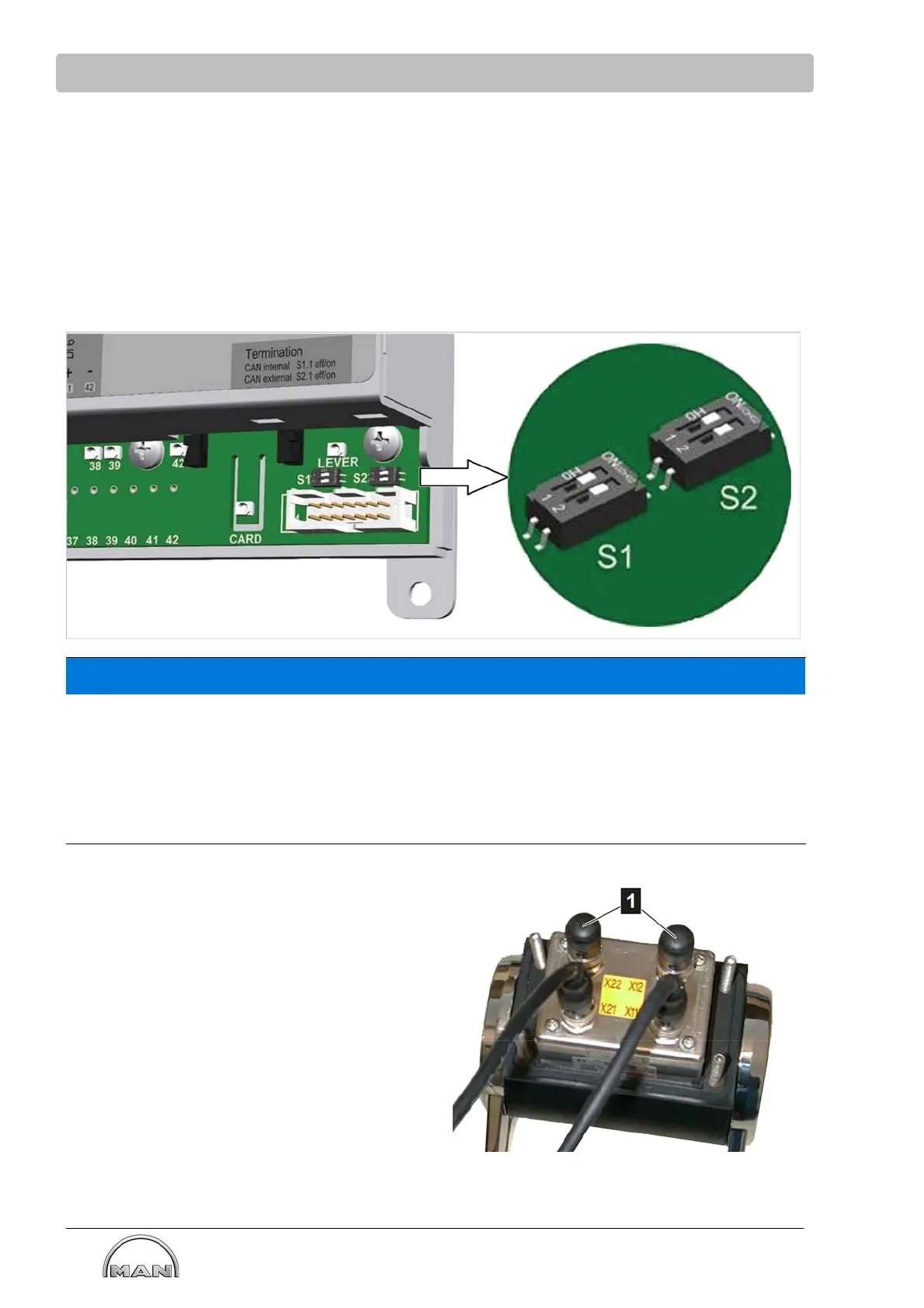
Terminating resistors
The drive levers communicate with the drive lever control unit in the E-box in the engine room via a CAN
bus. This CAN bus must always be supplied with a terminating resistor at the start and the end.
Termination at the start of the bus in the engine terminal box
The control in the engine room has an internal terminating resistor (Dip switch S1) on the motherboard;
this must not be changed. Standard setting: S1 to the right.
S1: Drive lever terminating resistor switch
S2: Cross-communication terminating resistor switch
NOTICE
Malfunctions due to redundancy
The CAN termination of the cross-communication is realized on both sides via the DIP switch S2 set to
“ON”. The DIP switch S2 of the controls of the center motors must only be set to “OFF“ in the case of
systems with more than 2 engines.
For this reason:
S No terminating resistor may be inserted on the respective open plug X13 (e.g. starboard)/X14 (e.g. port).
Close open plugs with end caps.
Termination at the end of the bus on the drive
lever
The length of the CAN bus varies dependent
on the number of drive levers. In all cases,
the CAN bus must always be connected to the
last connected drive lever. To this end, the
120 ohm terminating resistor (1) is used.