GROVE 11-19
CD3340B/YB4411 STRUCTURAL
11
Published 04/07/2015 Control # 569-00
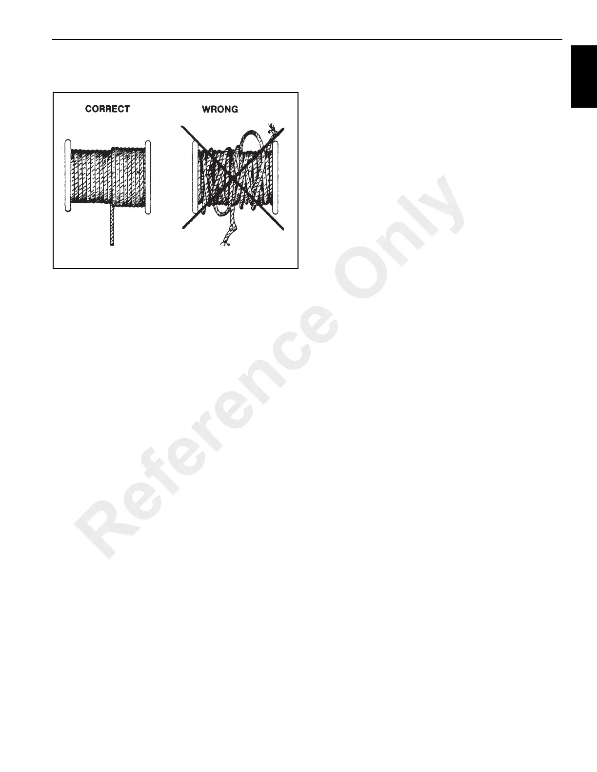
the drum. Loose windings will increase wear on the wire
rope and cause bad performance.
4. After installation, operate the hoist with a minimum load
until you see the wire rope is moving easily over the
sheaves and is winding correctly on the hoist drum.
5. Gradually increase the speed and load until the wire
rope is moving at normal load and speed. This run-in
period adjusts the moving parts to each other.
MAIN HOIST
Theory of Operation
The main hoist design is composed of high speed, low
torque gerotor motor, driving through a multiple disc brake,
and a pair of planet gear sets to the cable drum.
The multiple disc brake is spring applied and hydraulically
released through a port in the brake housing. During inhaul
(Figure 11-31) the brake is not released, since the load is
driven through a one-way cam clutch, bypassing the brake.
When the load comes to a stop, the cam clutch locks up and
the load is prevented from moving by the brake.
During payout (Figure 11-32), a brake valve is used to
prevent the load from moving faster than desired. This brake
valve partially blocks the main line from the motor back to the
control valve, allowing only a limited amount of oil through
the motor. The brake valve modulates by sensing pressure
on the other main line from the main control valve to the
motor. Also, any time there is sufficient pressure to modulate
the brake valve, this same pressure releases the multiple
disc brake.
Reference Only

 Loading...


