GROVE 5-35
CD3340B/YB4411 MAINTENANCE
Published 04/07/2015 Control # 569-00
16. Fill the hydraulic tank with Mobil #424 hydraulic oil to the
bottom of fill stainer or to sight gauge.
17. After the tank is filled, start the engine and operate each
function until all the cylinders and lines are filled.
18. Fully retract and lower the boom and retract the
outriggers. Check the hydraulic oil level. Oil must be to
the bottom of the fill strainer. Add hydraulic oil if
necessary.
19. Visually check for leaks.
Replace the Hydraulic Oil Filter
1. Engage the parking brake and shut off the engine.
2. Remove the side panel to expose the hydraulic
compartment and the hydraulic filter (Figure 5-76).
3. Remove the filter:
a. Using a filter wrench, turn the filter counterclockwise
to loosen and remove the filter. Properly discard the
removed filter.
b. Clean the mounting surface on the filter head for the
filter seat.
4. Install the filter:
a. Apply a small amount of clean hydraulic oil to the
gasket of the new hydraulic filter. Install the filter to
the filter head by turning it clockwise until the filter
gasket makes contact. Then, tighten the filter 1/2 to
3/4 turn to achieve a tight seal.
b. Start the engine and check for leaks around the
filter.
Check Swing Gear/Pinion Backlash
1. Remove the cover to expose the swing pinion and ring
gear.
• Rotating gears can cause injury. Keep hand clear of
rotating pinion and gear while the mast is rotating.
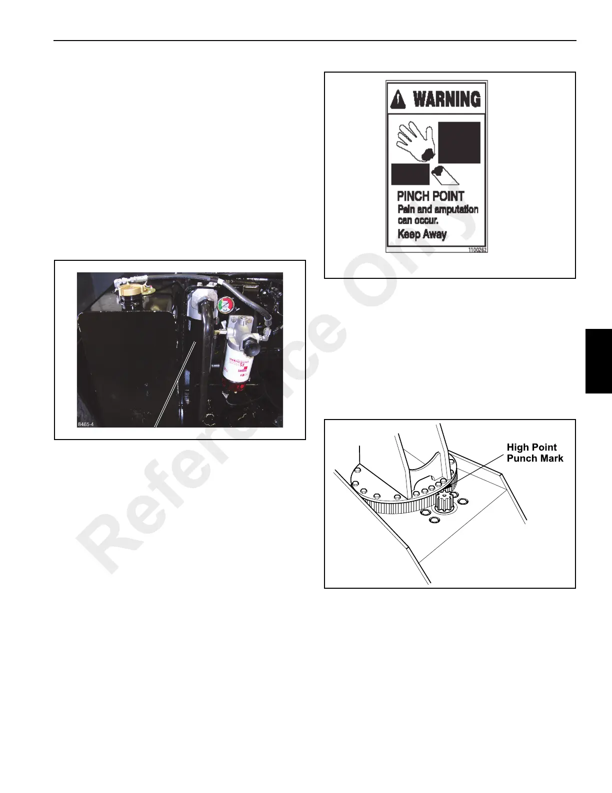
2. Start the engine and rotate the mast until the high point
on the swing gear is in alignment with the pinion. The
high point is punch-marked on the edge of the mast
base plate (Figure 5-77).
3. Using a feeler gauge, check the backlash between the
gear and pinion. There should be no clearance between
the swing gear tooth and the pinion tooth. If there is any
clearance, adjust the backlash. See Section 11.
2000 Hours Of Operation/Yearly
NOTE: You must read and understand the warnings and
basic safety rules, found in Safety Practices page
2-1 of this manual, before performing any operation
or maintenance procedures.
For additional engine maintenance guidelines, see
the engine manual furnished with this crane.
8465-4
FIGURE 5-76
Hydraulic Filter
Reference Only
 Loading...


