ELECTRIC SYSTEM CD3340B/YB4411
3-10
Published 04/07/2015 Control # 569-00
ACCESSORY CIRCUITS
Anti-Double Blocking System
General
This mechanism inhibits the hook block from being pulled
into the boom head during extension of the booms, raising of
the booms, and during hoist operation. When the hook block
actuates the limit switch on the boom head, oil flow to the
telescope cylinder, lift cylinder, and hoist motor is stopped. A
horn is activated to give a warning to the operator in all
cases. To move the hook block away from the boom head,
the operator must lower the hoist block, retract the boom or
lower the boom.
Circuit Description
See the wiring diagrams in Schematics/Wiring Diagrams.
Power is made available through a 20 amp fuse to the circuit
relay under the console in the cab and to the limit switch on
the boom head. When the hook block reaches the upper
limit, the limit switch closes, energizing the relay. The
energized relay activates the three anti-double blocking
solenoid valves in the lift, telescope, and hoist circuits.
Electric Swivel
On machines with a load indicator and/or anti-double
blocking system, an electrical swivel is installed at the center
of the mast rotation. The swivel gives electric current
continuity through full rotation of the mast.
Heater
The heater is a hot water heater and is connected into the
cooling system of the engine. An electric blower pushes air
through the heater core and into the cab. A defroster fan
blows air onto the windshield.
See the electrical wiring diagrams at the end of this manual
for the circuit. Power is available through a 15 amp fuse to
the heater/defroster switch in the instrument panel when the
ignition switch is in the ON position. The switch is a three
position switch (HI, LO and OFF).
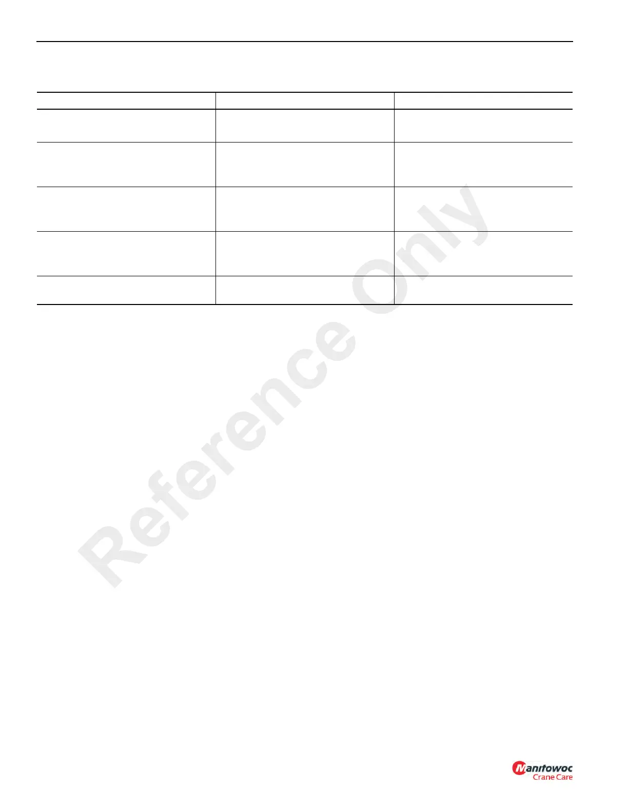
Table 3-3: Voltage Level Conditions
Voltage Measured Engine Speed Condition of Charging System
0-10 volts Stopped or low idle. Battery discharged.
Low battery charge.
11-12 volts Above low idle.
Stopped or low idle.
Problem in charging system. See
Troubleshooting - Charging System.
Normal battery charge.
12-14 volts Above low idle. Problem in charging system. See
Troubleshooting - Charging System.
Battery fully charged - no load.
14-16 volts Stopped or low idle. If indicator is between 14 and 15 volts,
the battery is newly charged.
Overcharged battery.
More than 16 volts Above idle. Overcharge. See Troubleshooting -
Charging System
Reference Only