HYDRAULIC SYSTEM CD3340B/YB4411
4-36
Published 04/07/2015 Control # 569-00
Installation
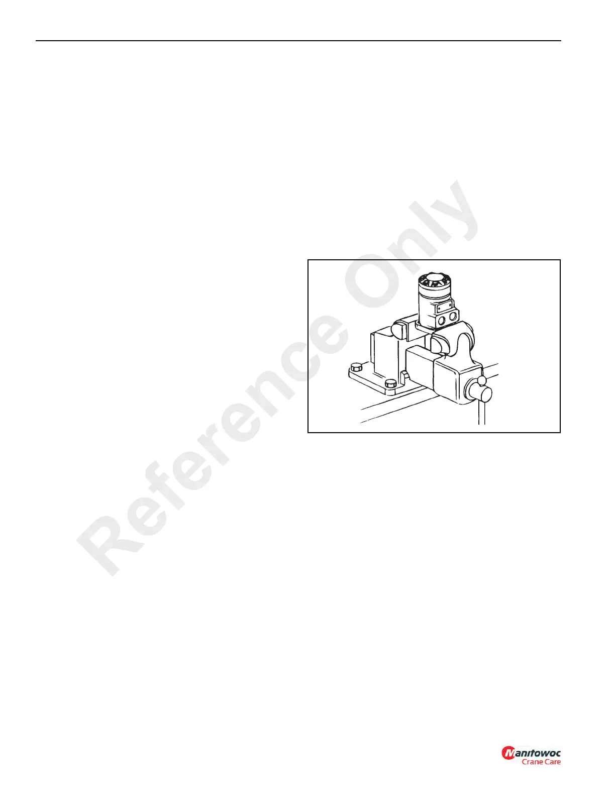
1. If complete valve assembly is being installed, put the
valve assembly in position and secure it with four
capscrews, washers and nuts. Connect the hydraulic
lines to the manifold block and connect the wire leads to
the solenoids.
2. If a valve section is being installed, place the valve
section in position and fasten with four socket head
capscrews. Connect the wire leads.
3. Connect the battery cables to the battery. Positive cable
first; negative cable second.
4. Start the engine and check outriggers for correct
operation. Check for leaks and add hydraulic oil to the
hydraulic tank, if necessary.
Swing Motor
Removal
1. Shut off the engine, set the parking brake and place
chock blocks at each wheel. Before disconnecting any
lines or hoses from the swing motor, let the system bleed
down for approximately 10 minutes after shutting off the
engine. Even then, disconnect the hose or line slowly to
release any pressure that still might be in the circuit.
NOTE: The swing motor can only be reached from under
the machine. Shut off the engine, set the parking
brake and remove the ignition key. Block all tires.
2. Before disconnecting the hydraulic lines, clean the port
area of the swing motor thoroughly. Disconnect the
hydraulic lines from the swing motor. Put caps and plugs
on the hoses and ports to keep dirt out.
3. Remove the two mounting socket head capscrews and
lockwashers from the swing motor. Remove the swing
motor and gasket. Discard the gasket.
Disassembly
NOTE: Cleanliness is extremely important when repairing
the swing motor. Work in a clean area. Plug the
ports then use a wire brush to remove foreign
material and debris from around the external joints
of the motor. Check the shaft and key slot, remove
all nicks, burrs or sharp edges that might damage
seals during installation. Before starting the
disassembly procedures, drain any remaining oil
from inside the motor.
1. Place the motor in a vice and clamp across the edges of
the flange (Figure 4-23) with the output shaft facing
down. When clamping use protective devices on the
jaws, such as soft jaws, pieces of rubber or wood.
NOTE: Although not all drawings show the motor in a vice,
it is recommended that you keep the motor in the
vice during disassembly and assembly. Follow the
clamping procedure explained in Step 1.
2. Remove seven capscrews (19, Figure 4-24) and seal
washers (18).
3. Remove end cap (17). Remove and discard seal (13)
from the end cap.
4. Remove gerotor (16). Remove and discard seal (13)
from the gerotor.
5. Remove drive shaft (14).
Reference Only