GROVE 4-35
CD3340B/YB4411 HYDRAULIC SYSTEM
Published 04/07/2015 Control # 569-00
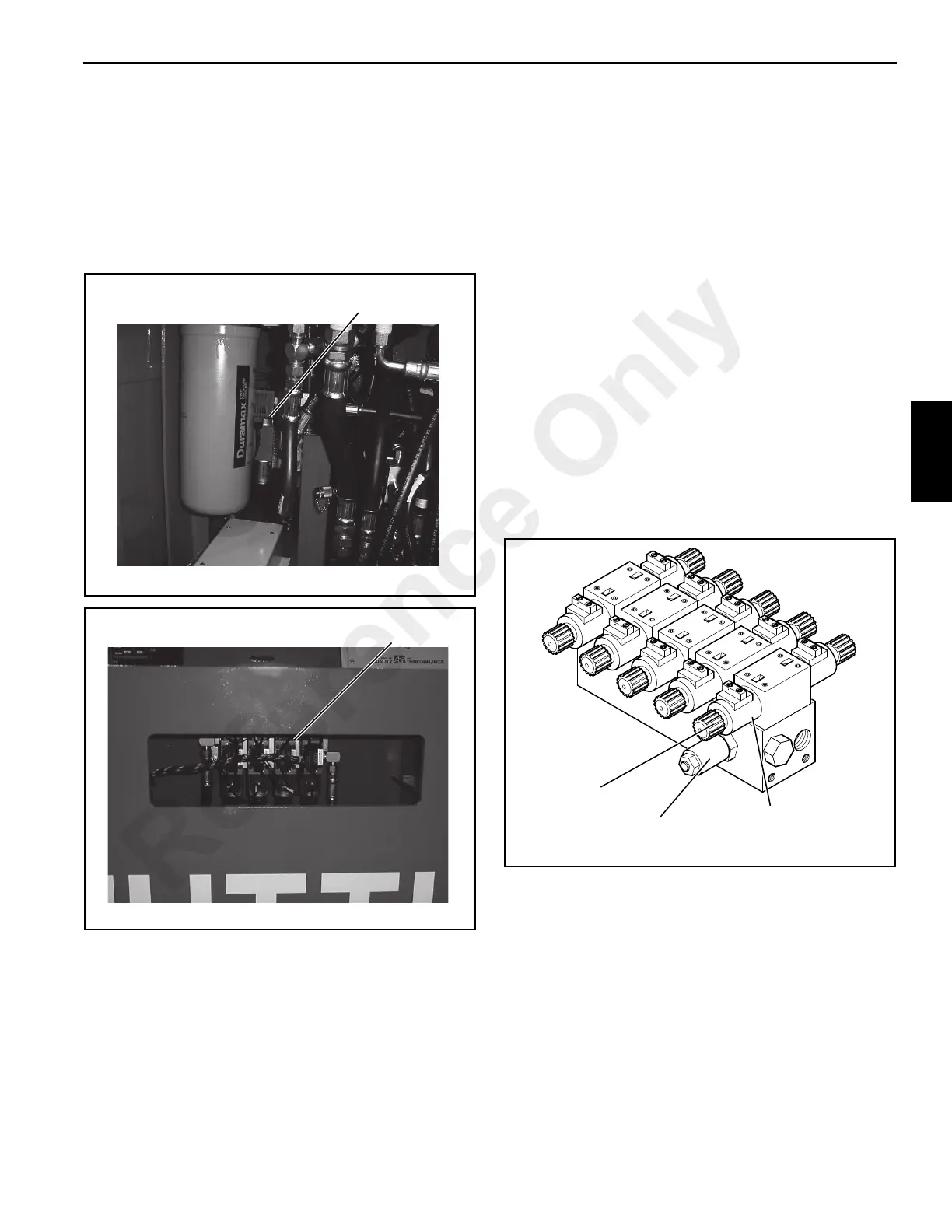
3. Standard Outriggers - Remove the side panel to gain
access to the valve area (Figure 4-20).
Independent Outriggers - Access to the valves can be
obtained through the cutout opening in the front plate of
the crane (Figure 4-21).
Independent Outriggers with Auxiliary Front Winch - The
front top deck plate must be removed to gain access to
the valve.
4. Individual sections can be removed from the manifold
block without removing the complete valve. Disconnect
the electrical leads from the outrigger valve solenoids.
Remove the four socket head capscrews securing the
valve section to the manifold block. Remove the valve
section.
5. If the complete valve assembly must be removed, tag all
hydraulic lines for correct assembly. Clean the valve and
connecting lines. Disconnect the hydraulic lines from the
valve ports. Put plugs in the hose ends and cap the
valve ports to keep dirt out of the hydraulic system.
Remove the valve mounting screws and remove the
valve.
Solenoid Replacement
The solenoids on each valve section can be removed without
removing the valve section from the manifold valve.
1. Stop the engine and engage the parking brake. Place
chocks under the wheels.
2. Disconnect the battery cables from the battery. For
safety, disconnect the negative (-) cable first.
3. Gain access to the outrigger valve. See “Removal”
procedures on page 4-34.
4. Tag and then disconnect the wire leads from the
solenoid.
5. Remove the plastic nut (Figure 4-22) from the solenoid
shaft. Slide the solenoid off of the shaft.
6. Place the new solenoid over the solenoid shaft and
install the plastic nut.
7. Connect the wire leads to the solenoid.
8. Connect the battery cables. Positive cable first; negative
cable second.
9. Start the engine and test outrigger function.
10. Install any removed covers or plates.
FIGURE 4-20
p0812
Side Plate
Removed
FIGURE 4-21
p0803
Side Plate
Removed
FIGURE 4-22
a0494
Plastic Nut
Solenoid
Relief Valve
Reference Only