GROVE 4-27
CD3340B/YB4411 HYDRAULIC SYSTEM
Published 04/07/2015 Control # 569-00
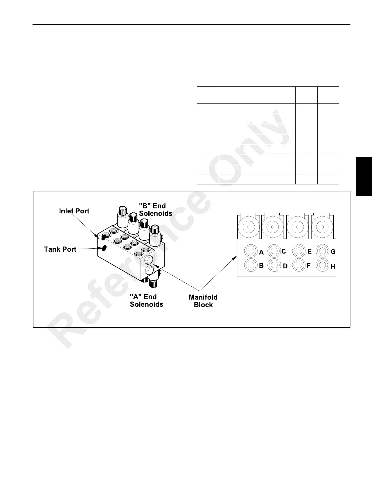
Outrigger Valve
Description
The outrigger valve consists of a manifold, relief valve, and
either four or eight solenoid valves, depending upon which
outrigger system is used on the crane.
Each solenoid valve has a closed-center passage, blocking
oil at the valve and preventing oil from returning to tank
unless the spool is shifted. Oil from the manifold inlet flows
directly to each valve section where it is stopped. When a
solenoid is activated, the spool moves allowing oil to flow
through the solenoid valve and manifold to the outrigger
cylinder. Return oil from the cylinder flows through the
solenoid valve and manifold back to tank.
A relief valve is installed in the inlet of the manifold and
protects the outrigger circuit from high pressure buildup.
Outrigger Valve Ports
For easy identification the ports are given in alphabetical
sequence, starting at the ports nearest the inlet and relief
valve.
Table 4-7
Port
Function
(Under High Pressure)
Sol. Wire
A Right Outrigger Down A J3
B Right Outrigger Up B J34
C Right Outrigger In A J15
D Right Outrigger Out B J25
E Left Outrigger In A J21
F Left Outrigger Out B J4
G Left Outrigger Down A J17
H Left Outrigger Up B J24
Reference Only