STRUCTURAL CD3340B/YB4411
11-66
Published 04/07/2015 Control # 569-00
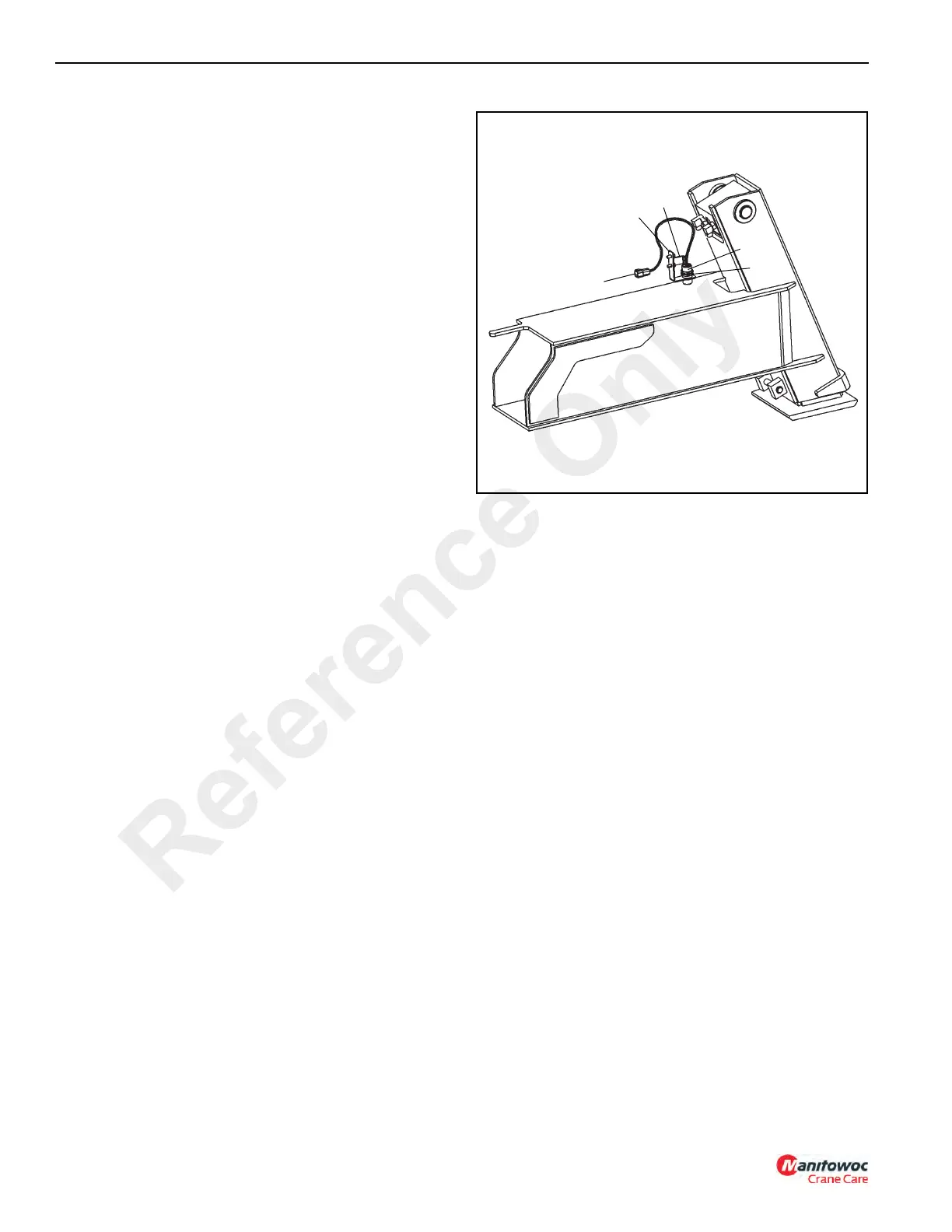
Outrigger Monitoring System (OMS)
(Optional—Standard in North America)
The Outrigger Monitoring System (OMS) proximity switches
(if equipped) are mounted outside the outrigger housing
tubes. The proximity switches identify whether an outrigger
beam is at the fully extended position or at any position less
than fully extended.
Removal
1. Disconnect switch cable (1, Figure 11-148) from
harness.
2. Remove switch mounting bracket (2).
3. Remove jam nuts (3) and thread switch (4) out of the
mounting bracket.
Installation
1. Feed cable through the mounting bracket and jam nuts.
2. Thread switch through mounting bracket.
3. Thread nuts on switch.
4. Thread switch up until it touches tab (5) of mounting
bracket and LED is pointed away from the bracket.
5. Tighten jam nuts against mounting bracket.
6. Adjust bracket and/or switch to have 3 to 10 mm (.12
to.38 in) gap between end of switch and outrigger beam.
7. Connect switch cable to wire harness.
Reference Only

 Loading...


