HYDRAULIC SYSTEM CD3340B/YB4411
4-10
Published 04/07/2015 Control # 569-00
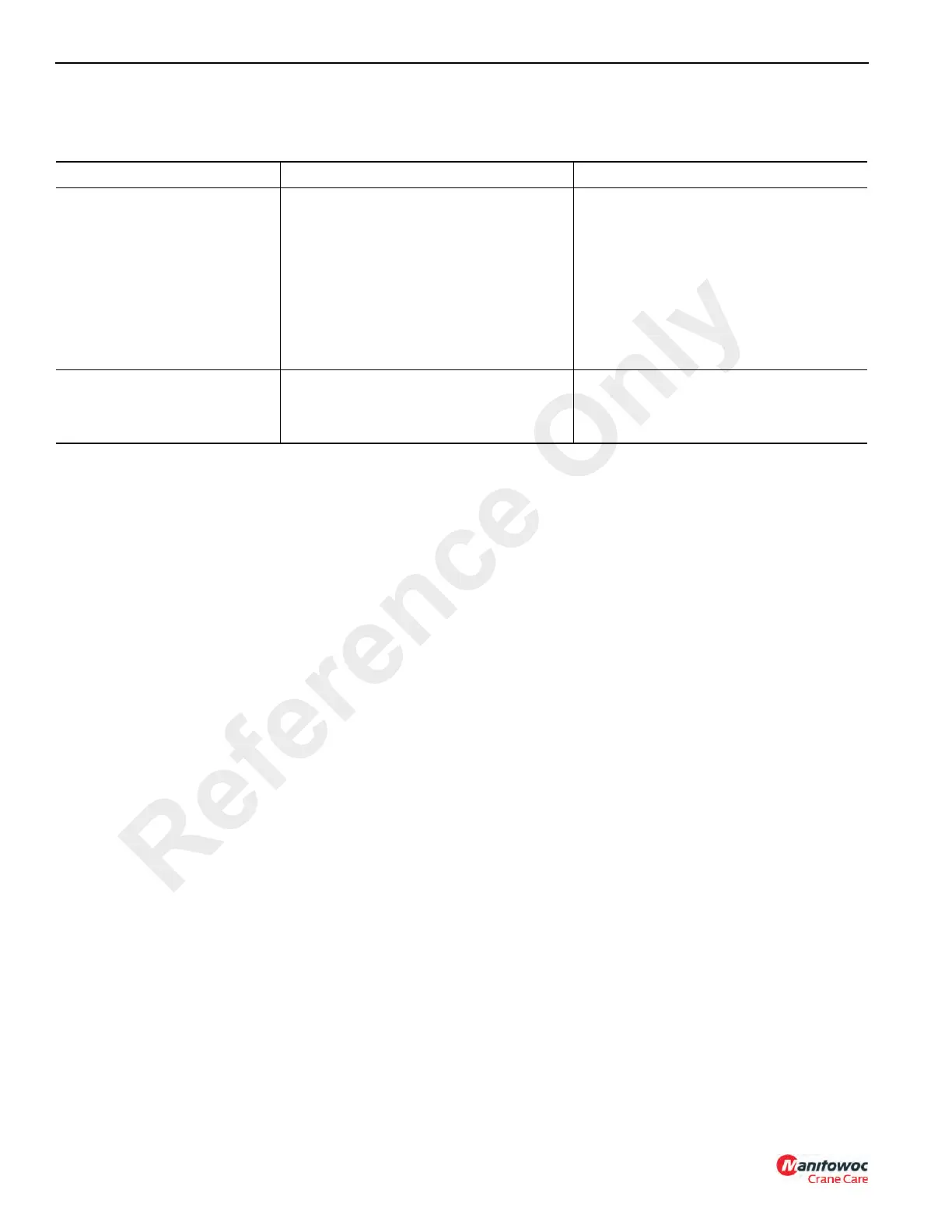
Swing Circuit Troubleshooting
Table 4-6
HYDRAULIC SYSTEM
System Description
The hydraulic system is a closed-center hydraulic system
with pressure compensated load sensing characteristics
driven by a variable displacement axial piston pump.
Hydraulic Pump
Description
The hydraulic pump is a variable displacement axial piston
pressure compensated pump. The pump generates a fluid
flow and imparts to that fluid the necessary pressure forces
to obtain the hydraulic system pressure.
The pump basically consists of the housing (1, Figure 4-1),
piston (2), shoes (3), port plate (4), drive shaft (5), swash
plate (6), shaft seal (7), compensator (8) and valve plate (9).
Rotation of the drive shaft (5) and control piston (not shown)
causes a linear piston movement as the piston shoe (3)
slides along the tilted swash plate (6). As the piston retracts
in the cylinder bore, hydraulic oil from the hydraulic oil tank
fills the developing vacuum cavity by way of the suction
kidney in the valve plate (9). At maximum retraction of the
piston, shaft rotation causes the piston to go beyond the
suction kidney and begin communication with the pressure
kidney. Continuing rotation then extends the piston into the
cylinder bore, forcing oil into the pressure port and out to the
hydraulic system.
Test - Pump Output
The hydraulic pump output can not be checked using a
flowmeter. The efficiency of the pump must be checked by
using function cycling speeds.
Pressure Regulation
System pressure is working on the pressure compensator
against a setting spring. When system pressure overcomes
the spring force, the spool shifts allowing system pressure
into the control piston. This causes the pump to stroke to a
regulating point sufficient to maintain the increased
compensator setting (system pressure) and the lubrication
fluid flow required.
When the system pressure setting is reached, only the
amount of fluid necessary to satisfy the load conditions is
delivered. If the load condition is such that no flow is
required, only cooling and lubricating fluid is delivered.
Power usage and heating of the fluid are kept to a minimum.
When the system pressure falls below the compensator
spring setting, spring force returns the spool back to the
normal position, which drains the control piston (2,
Figure 4-1) to the pump case drain. This causes the pump to
de-stroke, reducing the fluid flow to the level required.
Symptom Possible Cause Remedy
Mast will not rotate when the
swing control is actuated
Damaged or broken motor shaft.
Damaged or broken gearbox shaft or gear.
Faulty pump.
Leakage in hydraulic swivel.
Swing relief valve malfunction.
Dirt or restriction in swing relief.
Repair or replace the swing motor.
Overhaul or replace the gearbox. See
Maintenance, page 5-1.
Overhaul or replace the pump.
Replace seals in the swivel.
Check swing relief pressure. See
page 4-18.
Clean the relief valve.
Difficult or slow swing
Restriction in pilot control lines.
Friction or restriction in mast bearing.
Faulty swing motor or gearbox.
Check and repair.
See Maintenance, page 5-1.
Repair or replace.
Reference Only

 Loading...


