BRAKE SYSTEM CD3340B/YB4411
9-2
Published 04/07/2015 Control # 569-00
Table 9-4
PRIORITY FLOW CONTROL VALVE
DESCRIPTION
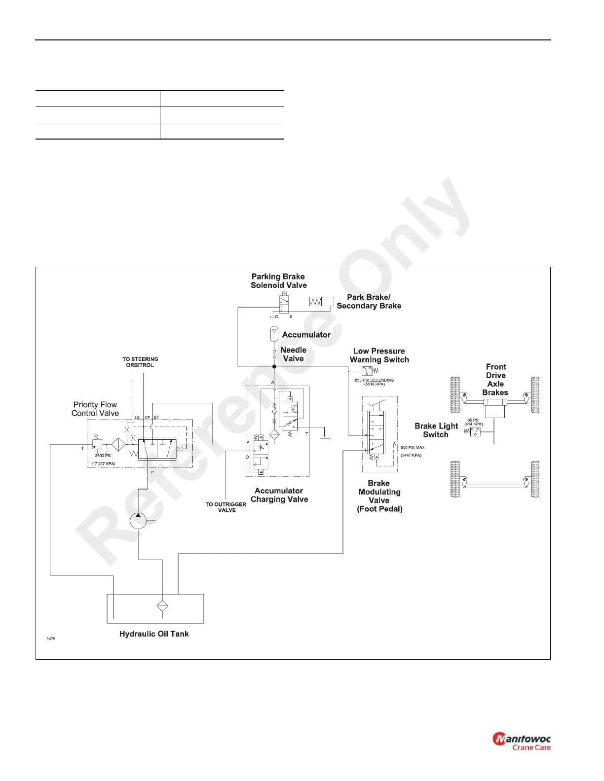
There are two brake systems used on the crane; the service
brake system and the parking brake system.
Service Brake System
The service brake system (Figure 9-1) consists of the
hydraulic pump, a relief valve included in the priority flow
control valve, an accumulator charging valve, a low pressure
warning switch, an accumulator, a needle valve, a brake
modulating valve, a brake light switch and the front axle
service brakes.
Description of Operation
Hydraulic Pump
The hydraulic pump supplies hydraulic oil flow to the priority
flow control valve (Figure 9-1).
Priority Flow Control Valve
The priority flow control valve in normal operation supplies oil
to the accumulator charging valve. If oil is required for the
steering operation the priority flow control valve shifts to
furnish flow to the steering system. (See Steering System,
page 10-1.) The priority flow control valve also includes the
relief valve used to protect the steering and brake systems.
Accumulator Charging Valve
The accumulator charging valve supplies oil to the
accumulator on demand. This is accomplished at a preset
rate at a selected pressure; neither of which is adjustable.
The flow to the downstream brake modulating valve will be
reduced fractionally for a short time when the accumulator is
Priority Flow Set At 12. 3 L/min (3.25 gpm)
Control Pressure 758 kPa (110 psi)
Relief Valve Setting 17 237 kPa (2500 psi)
Reference Only
 Loading...


