ENGINE AND ENGINE SYSTEMS CD3340B/YB4411
6-10
Published 04/07/2015 Control # 569-00
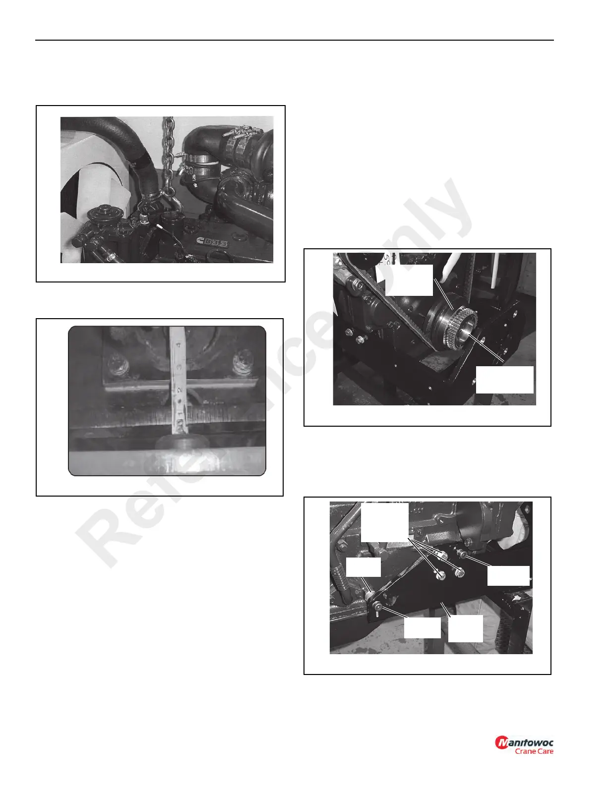
12. Attach a hook and chain to the engine and overhead
crane as shown in Figure 6-5. Between the chain and
overhead crane, attach a come-along.
13. Using the come-along, raise the engine a minimum of
13 mm (1/2 in). See Figure 6-6
NOTE: When raising the engine, watch for fan interference
with the engine shroud. Do not allow the fan to
come in contact with the shroud, damage to the fan
could occur. Also, watch for any other
interferences.
14. Remove two shoulder bolts (14, Figure 6-4). Remove
two shoulder bolts (9).
15. Remove eight capscrews (7) and flat washers (12).
Remove pump mounting bracket (8) and two spacers
(10).
16. Loosen clamping bolt (16).
17. Remove two socket head capscrews (13) from pump
coupling (6).
18. Remove pump coupling (6) and coupling sleeve (4).
19. Remove four capscrews (23) and then remove engine
coupling hub (5).
20. Remove six capscrews (17) and drive coupling (2).
Installation
NOTE: The following figures show the engine mounted in
an engine stand. Installation instructions are the
same for an engine installed in the machine.
1. Install adapter (2, Figure 6-4) using six capscrews (17),
as shown in Figure 6-7. Apply Loctite® 243 to the
capscrew threads and then tighten the capscrews to a
torque of 30 Nm (22 lb-ft).
2. Install engine coupling hub (5) using four capscrews
(23), as shown in Figure 6-7. Apply Loctite® 243 to the
capscrew threads and then tighten the capscrews to a
torque of 30 Nm (22 lb-ft).
3. Position pump bracket (8, Figure 6-4) into position as
shown in Figure 6-9. Apply Loctite® 243 to the threads
of six capscrews (7, Figure 6-4), then install the
capscrews along with six flat washers (12) into both
sides of the bracket. Do not tighten the bolts.
4. Coat the collar of shoulder bolts (14) with an anti-seize
compound. Apply Loctite® 243 to the threads of the
shoulder bolts and install them through the bracket into
FIGURE 6-7
p1433
Drive
Coupling
No.2
Engine
Coupling Hub
No.5
FIGURE 6-8
p1414
Bracket
Mounting
Capscrews
No.7
Pump
Bracket
No. 8
Shoulder
Bolt No. 14
Shoulder
Bolt No. 9
Spacer
No. 10
Reference Only
 Loading...


