GROVE 11-65
CD3340B/YB4411 STRUCTURAL
11
Published 04/07/2015 Control # 569-00
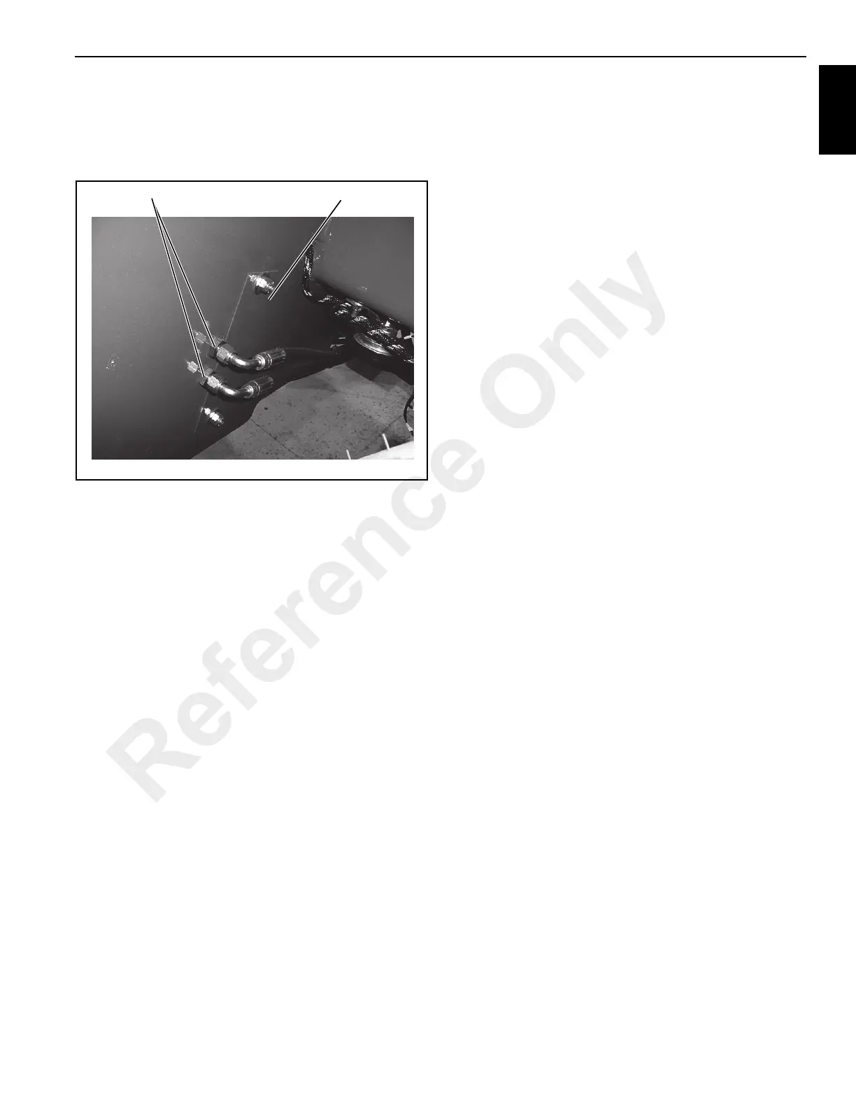
5. Disconnect the two hydraulic hoses for the vertical
outrigger cylinder from the bulkhead fittings attached to
the outside of the frame (Figure 11-147). Let the
hydraulic oil drain into a suitable container. Plug the
hoses.
6. Remove the access cover (Figure 11-147) and from
inside the frame housing, disconnect the two vertical
outrigger cylinder hoses from the bulkhead fittings.
7. Using a hoist, remove the outrigger assembly from the
frame.
Disassembly
1. Disconnect and remove the hydraulic hoses from the
elbows at the vertical outrigger cylinder (13,
Figure 11-146).
2. Remove the two elbows from the vertical cylinder ports.
Remove the counterbalance cartridge (14).
3. Remove a snap ring (8) from either side of pin (12).
Drive pin (12) out of the outrigger beam (6).
4. Pull outrigger inner box assembly (7) and vertical
outrigger cylinder (13) from outrigger beam (6).
5. Remove a retaining ring (8) from either side of pin (9).
Drive out pin (9) from outrigger inner box assembly (7).
6. Remove vertical outrigger cylinder (13).
Assembly
1. Completely clean outrigger beam (6, Figure 11-146) and
outrigger inner box (7). Use steam or suitable solvent.
Also, clean the slide contact surfaces on the main frame.
2. Lubricate the inside of the outrigger beam box and the
outside of the outrigger inner box assembly with STP Oil
Treatment, LUBAID NF, or bronze anti-seize compound.
3. Position the vertical outrigger cylinder (13) in the
outrigger inner box assembly (7). Align the rod end with
the mounting hole and install pin (9) and retaining rings
(8).
4. Align the inner box assembly and vertical outrigger
cylinder and insert the assembly into the outrigger beam
(6). Align cylinder mounting holes and install pin (12)
and retaining rings (8).
5. Install counterbalance valve (14) into vertical outrigger
cylinder (13). Install the elbows into the ports of the
vertical outrigger cylinder.
6. Connect the outrigger hoses to the elbows on the
vertical outrigger cylinder.
Installation
1. Lubricate the slide blocks inside the main frame with
STP Oil Treatment, LUBAID NF, or bronze anti-seize
compound.
2. Insert the outrigger assembly into the main frame far
enough to hold it in position.
3. Connect the hoses to the bulkhead fittings on the inside
of the main frame. Make sure the hoses are routed in the
top center of the outrigger beam and will not be
damaged when the outrigger is retracted.
4. Install the access cover and then connect the two hoses
to the bulkhead fittings on the outside of the frame.
5. Extend the rod of the outrigger horizontal cylinder and
align the mounting holes. Install pin (11, Figure 11-146)
and retaining rings (10).
6. Apply a thin layer of STP Oil Treatment, LUBAID NF, or
bronze anti-seize compound to the slide block contact
surfaces on the outrigger beam.
7. Operate the outrigger and check for correct installation.
Stop the engine and check for leakage at the hose
connections.
FIGURE 11-147
A0815
Access Cover
Bulkhead Fittings
Reference Only
 Loading...


