GROVE 4-41
CD3340B/YB4411 HYDRAULIC SYSTEM
Published 04/07/2015 Control # 569-00
Installation
1. Place a new gasket on the face of the swing motor
mounting flange.
2. Align the splines of the swing motor shaft with the
splines of the worm gear shaft of the swing gear box.
Install the swing motor to the gearbox with two socket
head capscrews and lockwashers.
3. Connect the hydraulic lines and fittings to the swing
motor.
4. Start the engine and slowly rotate the mast to remove
any air in the swing hydraulic circuit. Check for leaks.
Hoist Motor
Removal
1. Shut off the engine, set the parking brake.
2. Before disconnecting the hydraulic lines, clean the port
area of the hoist motor thoroughly. Disconnect the
hydraulic lines from the hoist motor. Put caps and plugs
on the hoses and ports to keep dirt out.
3. Loosen and remove the two capscrews and
lockwashers securing the motor to the hoist. Remove
the hoist motor and gasket. Discard the gasket.
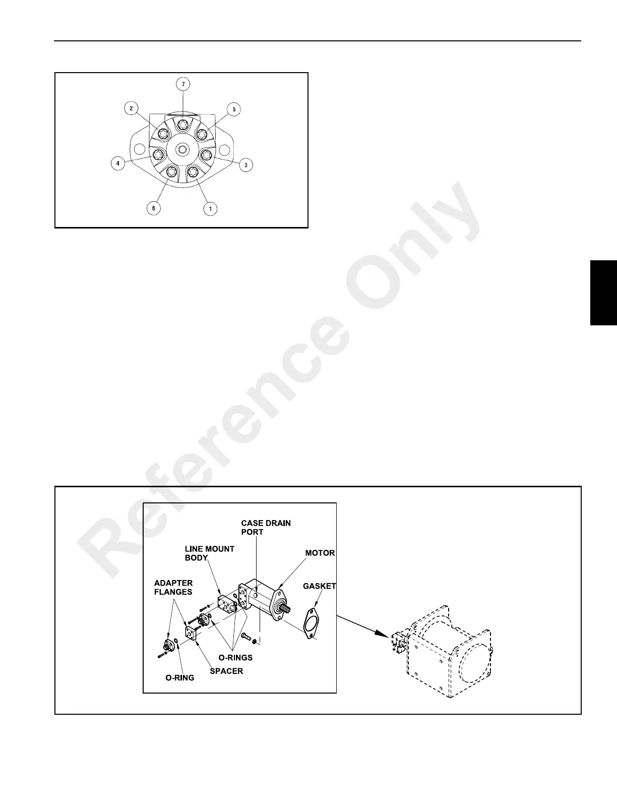
4. Remove the adapter flanges, spacer block and line
mount body (Figure 4-35) from the pump. Discard all O-
rings.
Disassembly
The hoist motor is not field serviceable. It must either be
replaced or returned to your distributor for repair.
Installation
1. Install the line mount body (Figure 4-35), spacer and
adapter flanges to the hoist motor. Be sure to use new
O-ring seals.
2. Install the hoist motor and new gasket to the hoist using
two capscrews and lockwashers.
NOTE: To inhibit cavitation and damage to the motor due
to lack of lubricating hydraulic oil, DO NOT start the
motor without first being filled with hydraulic oil.
3. Fill the hoist motor through the case drain hole
(Figure 4-35) to the bottom of the fill plug with clean
hydraulic oil.
4. Connect all the hydraulic hoses and fittings to the motor.
5. Start the engine and slowly run the boom hoist through
several cycles to remove any air in the system. Check
for hydraulic leaks.
Reference Only