GROVE 4-21
CD3340B/YB4411 HYDRAULIC SYSTEM
Published 04/07/2015 Control # 569-00
Supply Pilot Pressure Setting
1. Testing System Pressure
a. With the engine shutdown and the parking brake
set, install pressure diagnostic (Parker PD240) with
gauge onto pilot test port (3, Figure 4-7) of the
control valve.
b. Start the engine and actuate the crane power switch
and read the pressure indicated on the pressure
gauge. The gauge should read 28 ± 3.5 bar (400 ±
50 psi). If the pressure setting is correct shutdown
the engine and remove the pressure gauge. If the
pressure setting is incorrect, verify the supply
current to the crane power solenoid. This pressure
is not adjustable.
2. Shut down the engine and remove the pressure gauge.
Procedure for checking Tele Retract Pressure
1. With engine shutdown install pressure check diagnostic
quick disconnect (Parker PD240) with gauge onto load
sense test port the GLS port (2, Figure 4-5) located on
the front outrigger manifold.
2. Start the engine with the engine at full RPM pull the tele
retract lever till boom is fully retracted and hold pressure
should be 138 ± 10 bar (2000 ± 150 psi).This pressure is
non adjustable. Contact distributor if out of tolerance.
3. Shut down the engine and remove the pressure gauge.
ANTI-DOUBLE BLOCK SYSTEM
General
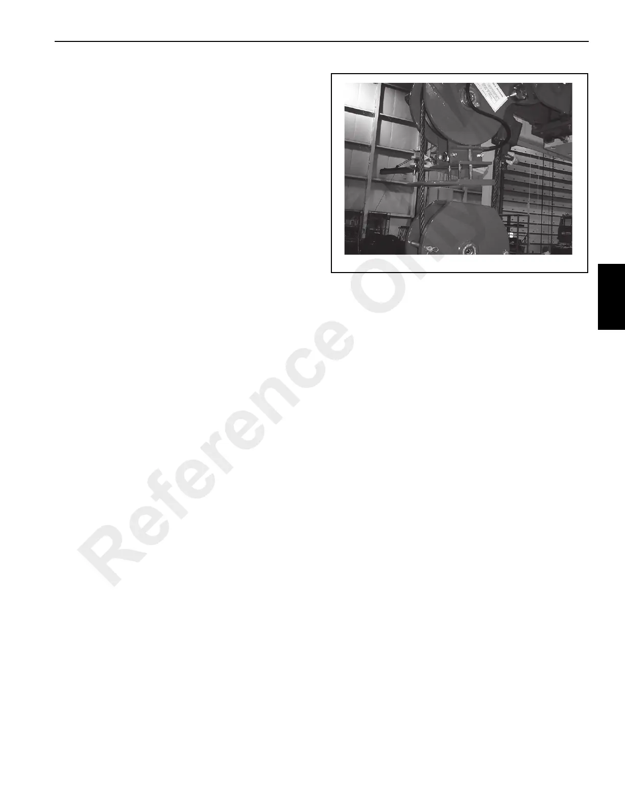
The anti-double block circuit protects the hoist, telescope
and lift circuits from damage in the event that the hoist block
comes in contact with the boom head causing a double
blocking situation. The anti-double block system includes an
anti-double block mechanism (Figure 4-9) at the end of the
boom head, a valve block with three normally closed
solenoids, and a check valve in the main control valve
sections for lift, telescope and hoist functions.
System Function
Refer to the hydraulic schematic at the end of this manual to
accompany the following text.
The main control valve sections for the hoist, telescope and
lift functions each have a check valve installed internally.
This check valve is connected to the return passage in the
valve section and to port A of the valve section. Its primary
function is to release hydraulic oil back to tank whenever the
anti-double block solenoid valves are open (de-energized).
During normal operation the solenoid valves are in the
closed (energized) position. In the closed position oil under
pressure is stopped by the solenoid valve from returning to
tank. The blocked fluid under pressure passes through a
restriction in the valve section to the check valve. The check
valve is held closed by a combination of the check valve
spring and oil pressure from the closed solenoid valve. In
combination, the oil pressure and spring pressure is greater
than the return oil pressure and the check valve is kept
closed. Return oil is then directed through the valve spool to
the outlet port of the control valve.
When the hoist block comes in contact with the anti-double
blocking bracket at the end of the boom head, the bracket
raises and actuates a switch. This switch, when actuated,
closes an electrical signal to the three solenoid valves
opening them. With the solenoid valves open, oil supply to
the check valve is reduced. The check valve spring alone is
not enough to hold the check valve closed, therefore, the
check valve opens. With the check valve open, hydraulic oil
which would normally flow to the lift cylinder, telescopic
cylinder or hoist motor through port A of the valve section is
returned through the check valve to the outlet of the control
valve, or through the open solenoid valve, back to tank.
Lowering the hoist block will deactivate the switch to close
the solenoid valves and return flow through port A to the
function.
Reference Only

 Loading...


