GROVE 11-31
CD3340B/YB4411 STRUCTURAL
11
Published 04/07/2015 Control # 569-00
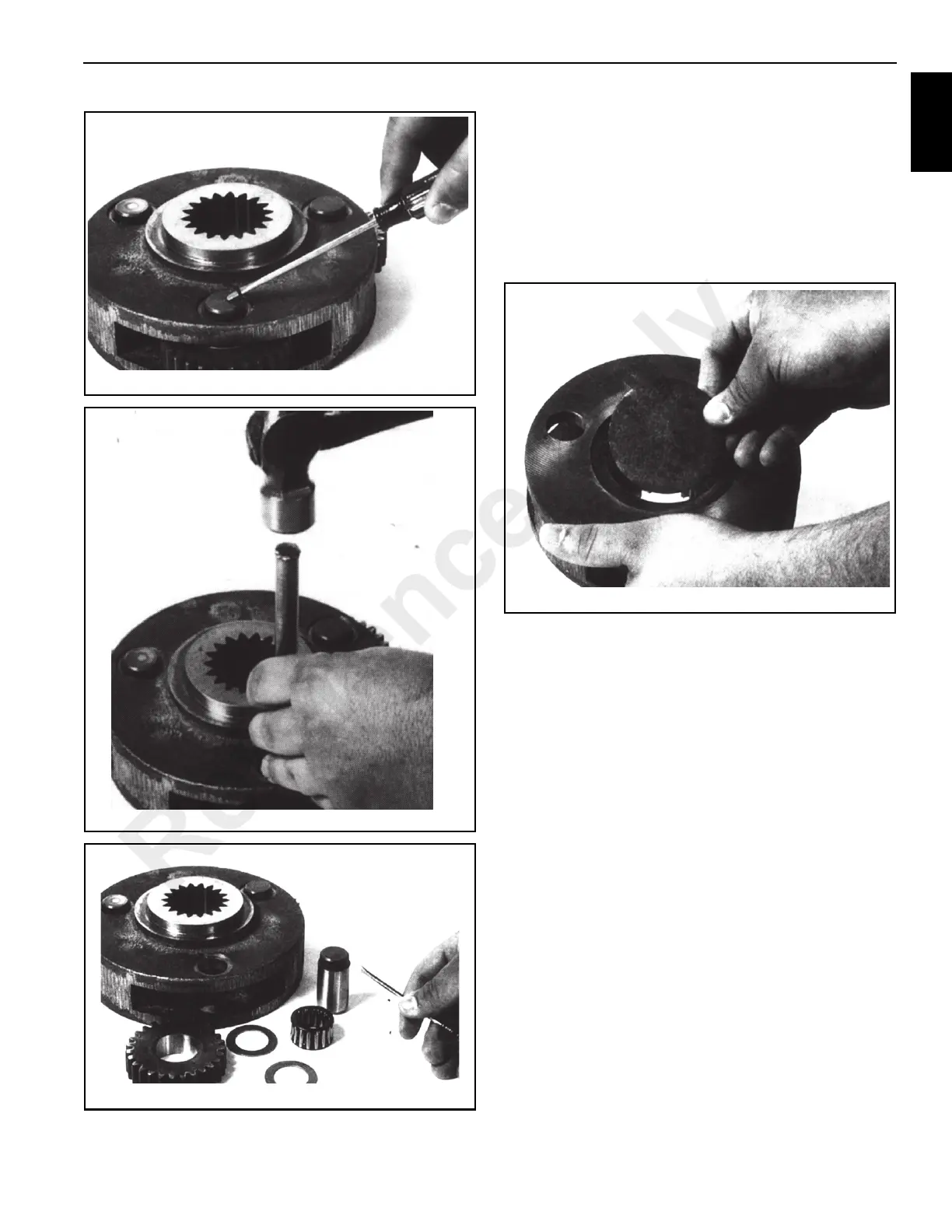
3. Remove the planet gears (2), thrust washers (7) and
bearings (6) from the carrier (1). See Figure 11-65.
4. Inspect the pins, bearings and gear bores for evidence
of wear and replace if necessary.
5. On the output planet sets, note that two bearings (10)
with a spacer (13) between them are used.
6. Before assembling the planet sets. Be sure to insert the
plugs in the carriers (Figure 11-66).
7. To assemble the planet sets, be careful to line up the
planet pins with the thrust washers and bearing and then
press the knurled part of the pin into the carrier. If the
pins are not lined up properly, the thrust washers can be
shattered during the pressing operation.
MAIN HOIST
(BRADEN MODEL)
Description of Hoist
The hoist (Figure 11-67) has four basic component parts:
1. Hoist base
2. Hydraulic motor subassembly
3. Brake cylinder and motor support
4. Drum assembly
The drum assembly consists of three assemblies:
1. Drum with internal ring gear
2. Output planetary gear set
3. Primary planetary gear set.
The hydraulic motor is bolted to the motor support which in
turn is bolted to the brake cylinder and the base. The motor
end of the drum, rotating on a ball bearing, is supported by
Reference Only
 Loading...


