STRUCTURAL CD3340B/YB4411
11-30
Published 04/07/2015 Control # 569-00
8. Install the cover onto the brake housing and draw it
down evenly, alternating between opposite capscrews.
Make sure that the cover is properly aligned with brake
housing to orient the motor as it should be.
9. Check the brake release with a portable pump. Full
release should be obtained at 1034 kPa (350 psi), plus
or minus 138 kPa (20 psi). Also, check the brake for
proper operation by applying 1929 kPa (280 psi) to the
brake port and adapting a torque wrench to input shaft.
The torque here in the payout direction should be 129.2
to 156.4 Nm (95 to 115 lb-in).
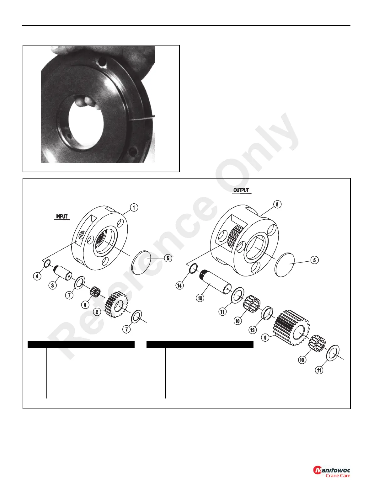
Planet Sets
1. Remove the retaining ring from the planet pins
(Figure 11-63).
2. Remove pins (3) from the carrier by carefully tapping
them out (Figure 11-64).
Item Description
1. Input Carrier
2. Planet Gear (3)
3. Planet Pin (3)
4. Retaining Ring (3)
5. Plug (2)
6. Bearing (3)
7. Thrust Washer (6)
8. Output Carrier
9. Planet Gear (3)
10. Bearing (6)
11. Thrust Washer (6)
12. Planet Pin (3)
13. Spacer (3)
14. Retaining Ring (3)
Item Description
FIGURE 11-62
a0480
Reference Only
 Loading...


