BRAKE SYSTEM CD3340B/YB4411
9-10
Published 04/07/2015 Control # 569-00
20. Install new lining (20) on piston (19) using new flat head
screws (21). Tighten screws to a torque of 3.4-4.5 Nm
(30-40 lb-in). Install new O-rings (18) on piston (19) and
insert lining and piston assembly (22) into housing (26)
bore.
21. Carefully install two new seals (28) in housing (26). Be
sure to install the seals the same direction as they were
removed.
22. Install bleed screw (30). Tighten to a torque of 12.2-20.3
Nm (9-15 lb-ft).
23. Install new O-rings (13 and 16) and new backup rings
(14 and 17) on piston (15). Be sure they are installed in
the correct order.
24. Install piston (15) into housing (26) bore. Be sure piston
is installed in the correct direction. Be careful not to
pinch the O-rings on the inlet ports.
25. Install new backup ring (10) and new O-ring (11) on
piston (9). Be sure they are installed in the proper order.
Install push rod (12) in bore of piston (9). Install piston
into housing (26) bore.
26. Fully lubricate the threads of adjusting screw (7) and
lock nut (9) and install into cover (3).
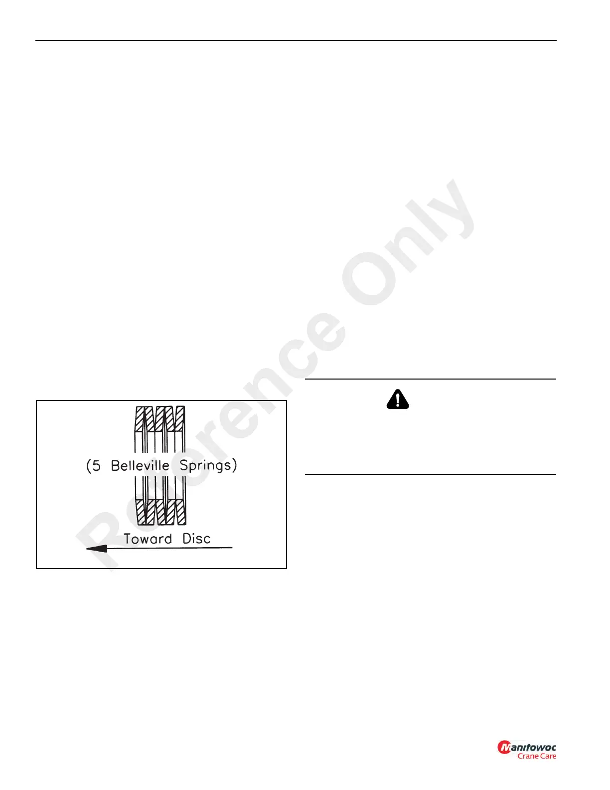
27. Install washer (6), if used, and new belleville springs (5)
over end of piston (9). Follow the stacking sequence
shown in Figure 9-12.
28. Install new seal (4) in cover (3). Be sure inside of cover
is coated with grease.
29. Install new gasket (23), cover (3), lockwashers (2) and
capscrews (1). Tighten the screws evenly in the order of
A, B, C and D as shown in Figure 9-11. When installed,
tighten each screw to a torque of 29.8-36.6 Nm (22-27
lb-ft).
30. Assemble the brake assembly onto the mounting
bracket (31).
31. Install the parking brake assembly onto the frame of the
crane.
32. Attach the hydraulic hose.
33. Adjust the lining clearance as described on page 9-5.
34. Open the accumulator needle valve and then bleed air
from the system as described on page 9-4.
NOTE: The needle valve must be in the open position for
the brake system to operate properly. If it is not
open, the charging pump will cycle every time the
brake pedal is depressed and if the crane’s engine
stops there may not be enough pressure to stop
the crane.
Seal Kit Installation
The parking brake has a seal kit available. It includes all the
parts necessary to replace all the seals in the brake. These
parts are indicated in Figure 9-10 with a symbol.
NOTE: The needle valve must be in the open position for
the brake system to operate properly. If it is not
open, the charging pump will cycle every time the
brake pedal is depressed and if the crane’s engine
stops there may not be enough pressure to stop
the crane.
NOTE: When removing seals and back-up rings be careful
not to scratch or mar the pistons.
The linings must be kept free of grease, oil, etc.
1. Close the needle valve located under the accumulator
(Figure 9-7). This will shut off hydraulic pressure to the
parking brake. Release system pressure by actuating
the service brake pedal until no resistance is felt. Then,
engage and disengage the parking brake to release its
pressure.
2. Slowly, loosen the hydraulic hose from the parking
brake. Some pressure may still be present in the
hydraulic hose. Let the pressure escape and then
remove the hydraulic hose.
3. Cap the hydraulic hose to prevent contamination from
entering the hydraulic system.
4. Loosen lock nut (8, Figure 9-10) and back off adjusting
bolt (7).
WARNING
Before replacing the parking brake seals, make sure that
the machine is on level ground. Place chocks on both
sides of the four tires. Remove the ignition key. If these
precautions are not adhered to, the crane could run you
over while performing the repair.
Reference Only
 Loading...


