GROVE 9-3
CD3340B/YB4411 BRAKE SYSTEM
Published 04/07/2015 Control # 569-00
charging. This does not noticeably affect the operation of
these components. Full system pressure is available to the
downstream components at all times, providing oil delivery
and pressure from the pump and relief valve are not
impeded.
The accumulator charging flow rates and upper and lower
pressure limits are set at the time of manufacture and are not
adjustable.
Low Pressure Warning Switch
The low pressure warning switch illuminates a red light on
the dash when the brake pressure goes below 5861 kPa
(850 psi). When the red light illuminates, there still is enough
pressure for brake application to stop the crane. After which,
the brake system must be checked and repaired.
Accumulator
The accumulator is a hydro-pneumatic, piston-type
accumulator. This means that the accumulator is charged
with nitrogen and stores hydraulic fluid to a pressure of
13790kPa (2000 psi) for brake system usage.
Needle Valve
The needle valve is used during service of the brake system.
When closed, It shuts off the hydraulic supply from the
accumulator, holding a pressure in the accumulator. This
eliminates the need to charge the accumulator after brake
system service.
NOTE: The needle valve must in the open position for the
brake system to operate properly. If it is not open,
the charging pump will cycle every time the brake
pedal is depressed and if the crane’s engine stops
there may not be enough pressure to stop the
crane.
Brake Modulating Valve
The brake modulating valve is a closed-center spool design.
When the valve is in no-applied position, brake port (A,
Figure 9-1) is open to tank port (T). As the valve is initially
actuated, tank port (T) is closed off from brake port (A).
Additional actuation opens pressure port (P) to brake port
(A). More input force will increase the pressure to brake port
(A) until actuation effort and hydraulic reaction forces are
balanced. When actuation is released, the valve returns to its
non-applied position.
Brake Light Switch
The brake light switch illuminates the brake lights when the
brake modulating valve builds system pressure to 552 kPa
(80 psi).
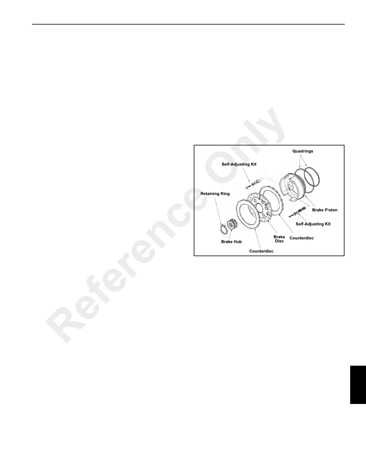
Front Axle Brakes
The front axle brakes are self-adjusting oil immersed and are
located on both sides of axle center housing (Figure 9-2).
Each brake assembly consists of one brake disc and two
counterdiscs. The brakes are applied when the brake
modulating valve is actuated. Hydraulic fluid under pressure
reacts against the brake pistons, forcing the brake
counterdiscs against the brake disc, slowing and/or stopping
the crane.
Parking Brake System
Description of Operation
The parking brake system consists of two-way switch in the
instrument panel, a solenoid valve and a parking brake. The
system connects into the service brake system (Figure 9-1)
and uses the accumulator for system pressure.
Parking Brake
The parking brake is a disc-type brake (Figure 9-3). The
brake disc is attached to the input shaft of the front axle. The
brake is attached to the frame behind the front axle. When
the parking brake switch is placed in the engage position,
hydraulic supply is shut off to the parking brake and the
springs in the parking brake apply the brake pads against the
brake disc, holding the crane from moving.
Reference Only
 Loading...


