GROVE 11-29
CD3340B/YB4411 STRUCTURAL
11
Published 04/07/2015 Control # 569-00
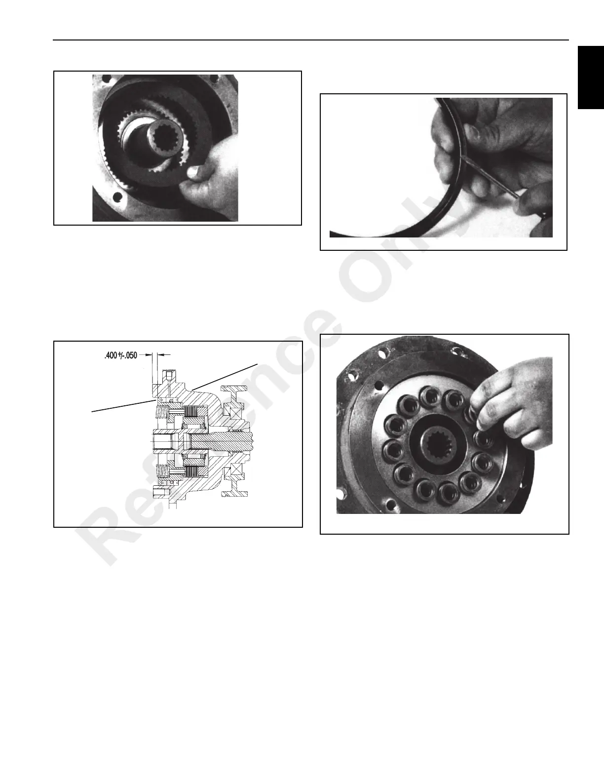
After installing plates and discs, set piston in place and
check the brake stack-up to make sure that the
dimensions are within the tolerance shown in
Figure 11-58. If the measurement is greater than shown,
either some friction plates have been left out, or the
friction plate discs are worn beyond acceptable
tolerances. If your measurement is less than shown, too
many plates or discs have been inserted or they are not
seated properly.
4. Inspect each new seal (8, Figure 11-46). Install one seal
into the bore of the brake housing with grooves facing
out Install the other seal with grooves facing in
(Figure 11-59).
5. Install the piston into the brake housing and gently tap it
down until it is seated.
6. Install the springs (Figure 11-60) into the spring pockets.
If working in a horizontal position, coat the bottom of
each spring with grease to keep them in place.
7. Coat a new O-ring (Figure 11-61) with light oil and install
the O-ring into the groove on the brake cover.
FIGURE 11-58
A0479
Brake
Piston
Brake
Housing
Reference Only

 Loading...


